background image

Turbo-Cool 6” Recirculating Evaporative Cooling System Manual

9

Evaporative Cooling System Installation

Splash Plate and Pipe Hanger Installation

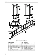
Secure the Splash Plates to the upper stringer, using a 10-16x1-1/2” screw at each 
end.

Note:

 The end holes in the Splash Plate must align with the chalk line and the end 

of the first Splash Plate must be flush with the inside of the end framing. See


Figure 3

.

Align the end mounting holes on the chalk line. See 

Figure 3

.

Secure the Pipe Hangers to the stringer, through the Splash Plate, using (2) 10-
16x1-1/2” screws. The lower hole in the Pipe Hanger should align with the chalk 
line on the stringer.
Hang remaining Splash Plates butting them tightly end to end. If the last Splash 
Plate is too long to fit within the end framing, cut as shown in 

Figure 3

.

Note:

 The Splash Plates are pre-drilled for installation and for accurate spacing 

and locating the Pipe Hangers.

Figure 3. Splash Plate & Pipe Hanger Installation

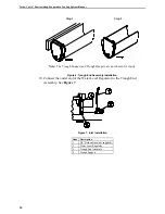
Trough Installation

The Trough must be secured to the lower stringer. See the Framing Installation 
section for stringer specifications.
1. Mark the Trough Support locations.

The first and last Trough Supports must be positioned flush with the inside of 
the framed opening. The bolt hole should be aligned on the chalk line. See 

Figure 4

Item

Description

1

10-16x1-1/2” Screw

2

Pipe Hanger

3

Splash Plate

4

Upper Stringer

5

Chalk Line

6

Flush with edge of end framing

7

Cut here if too long

Содержание Turbo-Cool

Страница 1: ...Turbo Cool 6 Recirculating Evaporative Cooling Installation Operator s Instruction Manual MV1438C October 1997 ...

Страница 2: ... maintenance shall not be considered defects under this warranty 5 This warranty applies only to systems for the care of poultry and livestock Other applications in industry or commerce are not covered by this warranty Chore Timeshall not be liable for any Consequential or Special Damage which any purchaser may suffer or claim to have suffered as a result of any defect in the product Consequential...

Страница 3: ...ation 6 I Framing Information 7 I Evaporative Cooling System Installation 9 I Splash Plate and Pipe Hanger Installation 9 I Trough Installation 9 I End Panel Installation 13 I Pad Support Installation 14 I Distribution Pipe Installation 14 I Sump Assembly Installation 15 I Sump Components Installation 16 I Evaporative Cooling Pan and Cover Installation 18 I System Start Up 20 C I System Operation ...

Страница 4: ...ld in Europe CE provides a benchmark for safety and manufacturing issues CE is required only on equipment sold in Europe Chore Time Equipment recognizes CE Mark and pursues compliance in all applicable products Fill in the CE Mark serial number in the blank space provided for future reference CE mark serial number Distributor and Installer Information Please fill in the following information about...

Страница 5: ...th the safety alert symbol to identify the severity of the warning DANGER indicates an imminently hazardous situation which if not avoided WILL result in death or serious injury WARNING indicates a potentially hazardous situation which if not avoided COULD result in death or serious injury CAUTION indicates a hazardous situation which if not avoided MAY result in minor or moderate injury DANGER El...

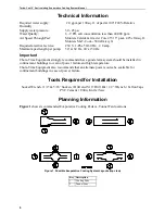
Страница 6: ...0 Hz 40 at 50 Hz Important Chore Time Equipment strongly recommends that a good alarm system should be installed in confinement buildings to warn of power failure and high temperature Chore Time Equipment also recommends that an alternate power source be available for confinement buildings in case of power failure Tools Required for Installation Socket Wrench 1 2 5 16 Sockets Drill and 5 16 Drill ...

Страница 7: ...lower 2 x 6 50 x 152 mm Stringer must be capable of supporting 30 lbs ft 4 2 kg m 2 Snap a chalk line on the lower stringer at the locations specified in Figure 2 Item 13 This chalk line will determine the location of the lag screws for the Trough Supports 3 Determine the location of the top stringer See Figure 2 Item 8 The distance between the top and bottom stringers should be approximately 1 1 ...

Страница 8: ... x 6 50 x 152 mm Bottom Stringer 3 15 38 cm Minimum Clearance 12 Pad Height plus 2 3 4 7 cm 4 30 36 76 91 cm Walkway 13 1 1 4 3 2 cm 5 6 15 cm Minimum Clearance 14 Bottom Stringer Chalk Line 6 2 x 6 50 x 152 mm Top Stringer 15 Top Stringer Chalk Line 7 Studs 16 24 61 cm for Sump Assembly 8 Pad Height less 1 1 2 38 mm 17 9 23 cm for Inlet Assembly 9 End Framing 18 7 1 2 19 1 cm Sump End Inlet End ...

Страница 9: ... line on the stringer Hang remaining Splash Plates butting them tightly end to end If the last Splash Plate is too long to fit within the end framing cut as shown in Figure 3 Note The Splash Plates are pre drilled for installation and for accurate spacing and locating the Pipe Hangers Figure 3 Splash Plate Pipe Hanger Installation Trough Installation The Trough must be secured to the lower stringe...

Страница 10: ...ort and Hanger Installation 3 The Trough should extend out past the last Trough Support at the Sump Assembly end at least 5 12 7 cm The Trough should extend out past the last Trough Support at the inlet end at least 1 2 5 cm The Trough will be cut to length after the End Assembly is installed Roll the Trough out flat on the floor below the Trough Hangers 4 Beginning at one end slide one side of th...

Страница 11: ...x nut Repeat steps 6 8 for each Trough Support 9 Wipe the inside of the Trough at the Trough End Assembly location to remove debris that may prevent proper sealing Position the End Assembly against the outside of the Trough Support at the inlet end of the Trough See Figures 6 7 Position the Adjustable Clamp directly over the Trough End Assembly orienting as shown in Figure 6 and tighten firmly Fig...

Страница 12: ...onnect the outlet end of the Water Level Regulator to the Trough End Assembly See Figure 7 Figure 7 Inlet Installation Item Description 1 3 4 Garden Hose not supplied 2 Water Level Regulator 3 Trough End Assembly 4 Trough Support Step 1 Step 2 Note The Trough Support and Trough Hangers are not shown for clarity ...

Страница 13: ...ion Pipe with the Pipe Hangers See Figure 8 Secure the Upper End Panels to the top stringer using the 10 16x1 1 2 Screws as shown in Figure 8 2 The Lower End Panels should overlap on the outside of the Upper End Panels to provide proper watershed 3 Align mounting holes in the upper and lower end panels and secure the end panels to the frame using the 10 16x1 1 2 Screws Figure 8 End Panel Installat...

Страница 14: ...cessary to glue the Distribution Pipes together IMPORTANT The spray holes in the Distribution Pipes MUST all be aligned and pointing straight up 3 Slide the straight end of the Distribution Pipe directly above the Sump Base through the End Panel since the bell will not fit through the End Panel hole and into the bell of the next Distribution Pipe 4 Verify that the spray holes are in alignment then...

Страница 15: ...p end of the Trough as shown in Figure 11 The Sump Base should set directly against the end Trough Support 2 Wipe the inside of the Trough at the sump end to remove debris that may prevent proper sealing Secure the Sump Base in the end of the Trough using an Adjustable Clamp as shown in Figure 11 Item Description 1 10 16 x 1 2 S S Screw 2 5 Distribution Pipe 3 2 Mechanical Gripper Plug 4 Framing 5...

Страница 16: ...1 2 PVC Pipe Item 6 will vary depending on desired Valve height pad height etc Note The 1 1 2 PVC Tee slips inside the bell of the Distribution Pipe Use teflon tape not supplied on threads as required Use PVC glue on slip connections Plug the electrical cord into the receptacle not supplied Note Make sure the vent hose inside the electrical cord is not obstructed Route the 1 4 Black Bleed Off Hose...

Страница 17: ...ription Item Description 1 1 1 2 PVC Tee 8 1 1 2 Union PVC Valve 2 1 1 2 x 3 4 PVC Reducer Bushing 9 1 1 2 Adapter Valve 3 3 4 Water Bleed Off Valve 10 1 3 H P 60 Hz Pump 4 Hose Barb Cap 11 Sump 5 1 4 Black Bleed Off Hose 12 1 1 2 Mechanical Gripper Plug 6 1 1 2 PVC Pipe 13 Sump Screen 7 Strainer 14 Overflow Drain ...

Страница 18: ...er to the directional arrows on the side of the pads GLACIER Pads May have a blue stripe which indicates the top end of pads and the air inlet side of the pads If no stripe is present refer to Figure 14to determine the proper pad orientation based on the direction of the pad flutes vs direction of incoming air flow Begin installing pads at either end Make sure the first pad is against the End Pane...

Страница 19: ...ocks onto the Pipe Hangers as shown in Figure 15 Step 2 4 Repeat steps 1 3 until all the Evaporative Cooling Pads are installed The Covers should butt end to end 5 The Evaporative Cooling Pads may be trimmed as required using a handsaw to fit inside the End Panels Figure 15 Cover and Cover Lock Installation Item Description 1 Cover 2 Distribution Pipe 3 Evaporative Cooling Pad 4 Cover Lock Step 1 ...

Страница 20: ...evel adjustment knob is on the back of the Regulator near the Chore Time logo To increase the water level turn the knob in the direction of the I or To decrease the water level turn the knob in the direction of the D or See Figure 17 Figure 17 Water Level Regulator 3 With the pump off i e unplugged Turn the Adjustment Knob on the Water Level Regulator Counter clockwise to raise the water level to ...

Страница 21: ...letely once every 24 hours to kill algae 4 Reduce the number of times the pad is wetted and dried out each day to maximize pad life 5 Clean the strainer and the sump screen regularly to maintian a sufficient supply of water to the pads 6 Periodically check the jets of water from the top of the Distribution Pipe The jets should spray approximately 8 to 11 20 to 28 cm straight upward 7 Keep the Dist...

Страница 22: ...4 1 2 Hose Barb Cap 24111 1 3 3 4 Bleed off Valve 9255 1 4 1 1 2 x 3 4 Reducer Bushing 38672 1 5 1 1 2 PVC Tee 38618 1 6 1 1 2 Sump Drain Plug 38476 1 7 2 Distribution Pipe Plug 38621 1 8 Screen 38619 1 9 Overflow Pipe 3 4 x 4 3 4 PVC 29107 6 1 10 Sump Tee Assembly 38471 1 11 Water Level Regulator 37147 6 1 12 S S Hose Clamp 38622 2 13 Trough End Assembly 38623 1 14 1 1 2 PVC Adapter 38627 3 15 1 ...

Страница 23: ...rative cooling line Item Description Part No Qty 5 Qty 20 1 Distribution Pipe 38616 1 4 2 Cover Lock 38352 2 8 3 Pipe Hanger 38351 2 8 4 Trough Support 38354 3 12 5 Trough Hanger 38353 3 12 6 Splash Plate 38357 1 4 7 Pad Support 38358 2 8 8 Evaporative Pad Cover 38355 1 4 5 16 x 1 1 2 SS Lag Screw 38617 3 12 5 16 18 x 1 2 SS Bolt 4412 17 3 12 5 16 18 SS Hex Nut 8543 3 12 5 16 Nylon Flat Washer 794...

Страница 24: ... 38733 2 1 2 Evap End Upper Panel L H 38356 2 1 3 Evap End Upper Panel R H 38356 1 1 4 Evap End Upper Panel R H 38356 2 1 5 Trough Support 38354 2 6 Trough Hanger 38353 2 7 1 1 2 x 5 PVC Pipe 38677 2 8 1 1 2 x 5 Distribution Pipe 38616 1 10 x 1 2 SS Screw 38613 18 10 x 1 1 2 SS Screw 36703 17 5 16 x 1 1 2 SS Lag Screw 38617 5 5 16 18 x 1 2 SS Bolt 4412 16 5 5 16 18 SS Hex Nut 8543 5 5 16 Nylon Fla...

Страница 25: ...oot System 30 foot System 35 foot System 40 foot System 45 foot System 50 foot System 38625 12 38625 17 38625 22 38625 27 38625 32 38625 37 38625 42 38625 47 38625 52 3 Cooling Pads Munters Celdek 45 15 3 foot 4 foot 5 foot 6 foot 38624 3 38624 4 38624 5 38624 6 Cooling Pads Munters Mi T Cool 45 15 3 foot 4 foot 5 foot 6 foot 38751 3 38751 4 38751 5 38751 6 4 Cooling Pads Glacier 45 15 3 foot 4 fo...

Страница 26: ...Turbo Cool 6 Recirculating Evaporative Cooling System Manual 26 ...

Страница 27: ...Turbo Cool 6 Recirculating Evaporative Cooling System Manual 27 ...

Страница 28: ...ved information about installing a plug on the Pump plug now supplied by vendor Contact your nearby Chore Time distributor or representative for additional parts and information CTB Inc P O Box 2000 Milford Indiana 46542 2000 U S A Phone 219 658 4101 E Mail ctb ctbinc com Printed in the U S A ...

Отзывы: