


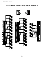


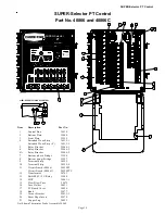


SUPER-Selector
‘
PT Control
Page 9
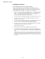
Unlabeled Master Selector Position
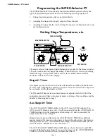
The unlabeled position (see the figure above) performs the following special setup
functions.
1. Telling the Control the number of sensors installed.
2. Calibrating the Sensors.
Do not attempt to perform these functions until you fully
understand these procedures.
GREEN - NORMAL
0
SET
3
2
5
6
RED - EDIT
ON TIME
OFF TIME
ON TIME
OFF TIME
LOW ALARM TEMP
HIGH ALARM TEMP
READ SENSOR
8
FAILED
SENSOR
6
5
OFFSETS
TEMPERATURE
9
8
7
SET
POINT
TEMP
AUX
3
2
STAGES
H1
H2
1
ALARM
4
10
STAGE #1 TIMER
TIMER
1
7
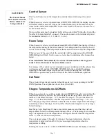
CONTROL SENSOR
STAGE #1
4
DISPLAY WINDOW
MASTER SELECTOR
STAGE SETTING
SENSOR SELECTOR
EDIT SWITCH
MV1041-15 10/96
Reset
Is Changed
Backups
Whenever
Set Point
Telling the Control the number of sensors installed.
1. Set the master selector switch to the unlabeled position. The display window will
show (- - - -) do not attempt to edit the display while (- - - -) is displayed. Set the
HEAT A switch one position left of ON. The display window will now show 1 for
a 40866 control and 0 for a 40866C control.
2. Use the Edit Switch to change the display to any number from 64 to 127.
3. The display window will then change to the number "3". This represents the fac-
tory setting of 3 sensors. This number may be increased up to 8 using the edit
switch. When the desired number of sensors is displayed, turn the edit switch to
the vertical "0" position.
4. The control has just been programmed for the number of sensors to be used.
To exit this function, turn the master selector switch to any setting outside the
unlabeled position and return the HEAT A switch to its appropriate setting.