Chore-Time SUPER-Selector PT 40866 Скачать руководство пользователя страница 5

SUPER-Selector


PT Control

Page 5

Control Sensor

The Control Sensor reads the temperature and determines which stage the control
is in. 

When the master selector is pointed toward CONTROL SENSOR, the display window 
will reflect which sensor is serving as the Control Sensor (any of the sensors may be 
chosen as the CONTROL SENSOR). Use the edit switch to choose which sensor is to 
be the Control Sensor. 

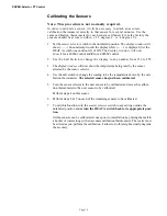
One to eight sensors may be installed. Refer to the section titled "Telling the Control the 
Number of Sensors Installed" on page 9. The positions used on the terminal strip must 
be in numerical order (i.e. 1, 2, 3, not 1, 3, 6, etc.).

Room Temp

When the master selector switch points toward READ SENSOR, the display will show 
the temperature reading of the sensor chosen. The reading cannot be edited by the edit 
switch
. It is a reading of the temperature at that sensor and is not subject to being edited.

Whenever any of the sensors fail, the alarm relay will be energized and the FAILED 
SENSOR light will flash. Use the sensor selector knob to determine which sensor has 
failed.

If the CONTROL SENSOR fails, the control will lock itself into the stage and 
mode it is in at the moment the sensor failure occurs

For instance, if the control is at set temp and in power ventilation with the exhaust fans 
cycling on and off, and the CONTROL SENSOR fails, the control will continue 
operating in that mode. Replacing the sensor, or simply changing the CONTROL 
SENSOR to a good sensor position will return the control to automatic operation.
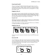
Set Point

The set point (desired temp) is edited when the master selector is pointing at the SET 
POINT position. The set point can be set from 0.0 to 200.0

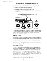
Stages: Temperatures & Offsets 

When the master selector switch is pointed toward OFFSETS the edit switch will set the 
temperature difference between the previous stage and the stage that is selected. For 
instance, if the offset for stage 1 = 2.0, the offset for stage 2 = 3.0, and the offset for 
stage 3 = 4.0, then the STAGE 3 absolute temperature will be Set Temp + 2.0 + 3.0 + 
4.0. Changing a temperature difference will affect the absolute temperature of that stage 
and all stages above that stage. It will not affect the absolute temperature of any stages 
below that stage.

Heat Stage 1 and Heat Stage 2 behave in a similar manner except that they are heat 
stages and are below the set temperature instead of above. The heat stages turn on at the 
stage’s temperature when the temperature is falling and then off when the temperature 
raises .3° from it’s turned on temperature.

The cool stages (stages 1 through 10) turn on at the stages temperature when the 
temperature is rising and turn off at the previous stages temperature when the 
temperature is falling. 

Pointing the master selector switch to TEMPERATURES causes the display to indicate 

CAUTION

The Control Sensor 

must be located in the 

bird or animal area 

being controlled.

Содержание SUPER-Selector PT 40866

Страница 1: ...OINT READ SENSOR FAILED SENSOR CHORE TIME EQUIPMENT P O BOX 2000 MILFORD INDIANA 46542 2000 SET POWER OUTPUTS ARE OFF IN TUNNEL 1 2 3 4 5 6 7 8 GREEN NORMAL RED EDIT ON TIME OFF TIME STAGE 1 TIMER H1...

Страница 2: ...ring issues CE is required only on equipment sold in Europe Chore Time Equipment recognizes CE Mark and pursues compliance in all applicable products Fill in the CE Mark serial number in the blank spa...

Страница 3: ...ance instructions specifically state otherwise Ground all electrical equipment for safety All electrical wiring must be done by a qualified electrician in accordance with local and national electric c...

Страница 4: ...te amount of time to program depends on bird age litter condition and the number of fans assigned to stage 1 Aux Stage 1 Timer The AUX STAGE 1 TIMER applies to the AUX A and AUX B outputs If an AUX A...

Страница 5: ...rol will continue operating in that mode Replacing the sensor or simply changing the CONTROL SENSOR to a good sensor position will return the control to automatic operation Set Point The set point des...

Страница 6: ...ode at a time power or tunnel These relays can be used to create special functions If it is desired to have the tunnel curtain s opening governed by static pressure while in tunnel mode the tunnel out...

Страница 7: ...uts A thru H except that they are routed through the AUX TIMER This feature is intended for foggers or cooling pads where it is desired to run them with a timer above the stage temperature If timing o...

Страница 8: ...ransitions Power to Tunnel It is important that the sensor chosen to be the control sensor is located in a position where the temperature does not decrease very much during the process of converting f...

Страница 9: ...ever Set Point Telling the Control the number of sensors installed 1 Set the master selector switch to the unlabeled position The display window will show do not attempt to edit the display while is d...

Страница 10: ...255 3 The display window will now show the temperature being read by the sensor selected by the sensor selector 4 Use the edit switch to change the reading to be the temperature shown by the cali bra...

Страница 11: ...ully realize the benefits of staging fans while in power ventilation mode Wiring the System Chore Time recommends limiting the load for each relay to 1 H P This is to help insure years of trouble free...

Страница 12: ...up system Obviously if the SUPER Selector PT alarm output is not functional it would be unable to send an appropriate signal to an alarm or other backup device s The only possible useful output of a n...

Страница 13: ...n one output with a single thermostat it is necessary to add a relay contact for each output backed up and drive the relay coil s from a single thermostat The figure below reflects a control with two...

Страница 14: ...ODE POWER MODE CLOSE TUNNEL CURTAIN IN K OUT IN M OUT IN IN OUT L OUT AUX IN A1 OUT N OUT A2 OUT IN A1 IN OUT B2 IN OUT B1 C OUT IN D OUT IN IN A2 OUT IN B1 OUT AUX AUX AUX HEAT OUT A IN OUT B2 IN B H...

Страница 15: ...UX AUX 4 8 4 5 4 4 4 7 4 9 4 9 4 9 4 9 4 6 A1 IN A2 IN OUT B1 IN OUT OUT IN C IN OUT B2 IN OUT E OUT IN F IN OUT IN OUT OUT I H IN OUT OUT IN IN J G D 8 16 SENSOR 3 8 5 2526 357 8 12 8 10 8 11 8 9 4 3...

Страница 16: ...T A1 A2 B1 IN IN OUT IN OUT OUT C B2 D E IN IN IN OUT OUT OUT IN AUX B1 AUX B2 IN OUT IN OUT A HEAT IN OUT B HEAT IN OUT SENSOR 4 SENSOR 3 2526 357 F H G IN IN IN OUT OUT IN OUT J SENSOR 5 2526 358 SE...

Страница 17: ...or PT Internal Wiring Diagram sheet 3 of 4 TUNNEL TUNNEL CURTAIN CLOSE CURTAIN TUNNEL OPEN 50 60 HZ CONTROL SENSOR 2526 356 1 SENSOR 2 IN OUT OUT MODE IN POWER MODE INPUT OUT OUT ALARM IN IN L2 OUT IN...

Страница 18: ...B1 A2 OUT OUT OUT OUT OUT IN IN B2 A B HEAT HEAT 2526 357 SENSOR 3 SENSOR 4 OUT OUT OUT AUX OUT 2 9 1 1 1 9 3 7 3 9 2 9 2 7 2 7 2 9 2 9 2 8 B1 A2 A1 IN IN IN OUT OUT OUT 2 8 2 9 B2 C D F E I H J SENSO...

Страница 19: ...F ON F 1 2 3 4 5 6 7 8 9 OFF ON G 1 2 3 4 5 6 7 8 9 OFF ON H 1 2 3 4 5 6 7 8 9 OFF ON I 1 2 3 4 5 6 7 8 9 OFF ON J AUX A 2 HP AUX B 2 HP K L M N SET POINT READ SENSOR FAILED SENSOR CHORE TIME EQUIPMEN...

Страница 20: ...e Time distributor or representative for additional parts and information Chore Time Equipment A Division of CTB Inc P O Box 2000 Milford Indiana 46542 2000 U S A Phone 219 658 4101 E Mail ctb ctbinc...

Отзывы: