Chore-Time SUPER-Selector PT 40866 Скачать руководство пользователя страница 16

SUPER-Selector


PT Control

Page 16

MV1532-6 12/97

TUNNEL

TUNNEL

CURTAIN

CLOSE

CURTAIN

TUNNEL

OPEN

50/60 HZ

CONTROL

OPEN

TUNNEL

CURTAIN

CLOSE

CURTAIN

TUNNEL

TUNNEL

K

IN

L

IN

OUT

OUT

M

N

IN

OUT

IN

OUT

AUX

A1

IN

OUT

AUX

A2

IN

OUT

A1

A2

B1

IN

IN

OUT

IN

OUT

OUT

C

B2

D

E

IN

IN

IN

OUT

OUT

OUT

IN

AUX

B1

AUX

B2

IN

OUT

IN

OUT

A

HEAT

IN

OUT

B

HEAT

IN

OUT

SENSOR

  #4

SENSOR

  #3

2526-357

F

H

G

IN

IN

IN

OUT

OUT

IN

OUT

J

SENSOR

  #5

2526-358

SENSOR

  #6

IN

OUT

OUT

I

OUT

SENSOR

2526-356

  #1

SENSOR

  #2

IN

OUT

OUT

MODE

IN

POWER

MODE

INPUT

OUT

OUT

ALARM

IN

IN

L2

OUT

IN

POWER

230V

L1

L1

L2

FUSED

230V

ALARM

MODE

POWER

MODE

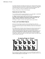
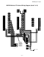
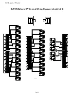
SUPER-Selector PT Internal Wiring Diagram (sheet 2 of 4)

Содержание SUPER-Selector PT 40866

Страница 1: ...OINT READ SENSOR FAILED SENSOR CHORE TIME EQUIPMENT P O BOX 2000 MILFORD INDIANA 46542 2000 SET POWER OUTPUTS ARE OFF IN TUNNEL 1 2 3 4 5 6 7 8 GREEN NORMAL RED EDIT ON TIME OFF TIME STAGE 1 TIMER H1...

Страница 2: ...ring issues CE is required only on equipment sold in Europe Chore Time Equipment recognizes CE Mark and pursues compliance in all applicable products Fill in the CE Mark serial number in the blank spa...

Страница 3: ...ance instructions specifically state otherwise Ground all electrical equipment for safety All electrical wiring must be done by a qualified electrician in accordance with local and national electric c...

Страница 4: ...te amount of time to program depends on bird age litter condition and the number of fans assigned to stage 1 Aux Stage 1 Timer The AUX STAGE 1 TIMER applies to the AUX A and AUX B outputs If an AUX A...

Страница 5: ...rol will continue operating in that mode Replacing the sensor or simply changing the CONTROL SENSOR to a good sensor position will return the control to automatic operation Set Point The set point des...

Страница 6: ...ode at a time power or tunnel These relays can be used to create special functions If it is desired to have the tunnel curtain s opening governed by static pressure while in tunnel mode the tunnel out...

Страница 7: ...uts A thru H except that they are routed through the AUX TIMER This feature is intended for foggers or cooling pads where it is desired to run them with a timer above the stage temperature If timing o...

Страница 8: ...ransitions Power to Tunnel It is important that the sensor chosen to be the control sensor is located in a position where the temperature does not decrease very much during the process of converting f...

Страница 9: ...ever Set Point Telling the Control the number of sensors installed 1 Set the master selector switch to the unlabeled position The display window will show do not attempt to edit the display while is d...

Страница 10: ...255 3 The display window will now show the temperature being read by the sensor selected by the sensor selector 4 Use the edit switch to change the reading to be the temperature shown by the cali bra...

Страница 11: ...ully realize the benefits of staging fans while in power ventilation mode Wiring the System Chore Time recommends limiting the load for each relay to 1 H P This is to help insure years of trouble free...

Страница 12: ...up system Obviously if the SUPER Selector PT alarm output is not functional it would be unable to send an appropriate signal to an alarm or other backup device s The only possible useful output of a n...

Страница 13: ...n one output with a single thermostat it is necessary to add a relay contact for each output backed up and drive the relay coil s from a single thermostat The figure below reflects a control with two...

Страница 14: ...ODE POWER MODE CLOSE TUNNEL CURTAIN IN K OUT IN M OUT IN IN OUT L OUT AUX IN A1 OUT N OUT A2 OUT IN A1 IN OUT B2 IN OUT B1 C OUT IN D OUT IN IN A2 OUT IN B1 OUT AUX AUX AUX HEAT OUT A IN OUT B2 IN B H...

Страница 15: ...UX AUX 4 8 4 5 4 4 4 7 4 9 4 9 4 9 4 9 4 6 A1 IN A2 IN OUT B1 IN OUT OUT IN C IN OUT B2 IN OUT E OUT IN F IN OUT IN OUT OUT I H IN OUT OUT IN IN J G D 8 16 SENSOR 3 8 5 2526 357 8 12 8 10 8 11 8 9 4 3...

Страница 16: ...T A1 A2 B1 IN IN OUT IN OUT OUT C B2 D E IN IN IN OUT OUT OUT IN AUX B1 AUX B2 IN OUT IN OUT A HEAT IN OUT B HEAT IN OUT SENSOR 4 SENSOR 3 2526 357 F H G IN IN IN OUT OUT IN OUT J SENSOR 5 2526 358 SE...

Страница 17: ...or PT Internal Wiring Diagram sheet 3 of 4 TUNNEL TUNNEL CURTAIN CLOSE CURTAIN TUNNEL OPEN 50 60 HZ CONTROL SENSOR 2526 356 1 SENSOR 2 IN OUT OUT MODE IN POWER MODE INPUT OUT OUT ALARM IN IN L2 OUT IN...

Страница 18: ...B1 A2 OUT OUT OUT OUT OUT IN IN B2 A B HEAT HEAT 2526 357 SENSOR 3 SENSOR 4 OUT OUT OUT AUX OUT 2 9 1 1 1 9 3 7 3 9 2 9 2 7 2 7 2 9 2 9 2 8 B1 A2 A1 IN IN IN OUT OUT OUT 2 8 2 9 B2 C D F E I H J SENSO...

Страница 19: ...F ON F 1 2 3 4 5 6 7 8 9 OFF ON G 1 2 3 4 5 6 7 8 9 OFF ON H 1 2 3 4 5 6 7 8 9 OFF ON I 1 2 3 4 5 6 7 8 9 OFF ON J AUX A 2 HP AUX B 2 HP K L M N SET POINT READ SENSOR FAILED SENSOR CHORE TIME EQUIPMEN...

Страница 20: ...e Time distributor or representative for additional parts and information Chore Time Equipment A Division of CTB Inc P O Box 2000 Milford Indiana 46542 2000 U S A Phone 219 658 4101 E Mail ctb ctbinc...

Отзывы: