


SUPER-Selector
‘
PT Control
Page 2
Support Information
(CE-mark serial number)
The Chore-Time SUPER-Selector PT Control is designed to be used as a tool to manage
ventilation in poultry and livestock applications. Using this equipment for any other
purpose or in a way not within the operating recommendations specified in this manual will
void the warranty and may cause personal injury and/or death.
This manual is designed to provide comprehensive, wiring, operation, and parts listing
information. The Table of Contents provides a convenient overview of the information in
this manual. The Table of Contents also specifies which pages contain information for the
sales personal, installer, and customer (end user).
IMPORTANT: CE stands for certified Europe. It is a standard which equipment must meet or exceed in order to
be sold in Europe. CE provides a benchmark for safety and manufacturing issues. CE is required only on
equipment sold in Europe.
Chore-Time Equipment recognizes CE Mark and pursues compliance in all applicable products. Fill in the
CE-Mark serial number in the blank space provided for future reference.
Include the names and address of your Chore-Time Distributor and installer.
Fill in the following information about your system. Keep this manual in a clean, dry place for future reference.
Distributor’s Name
Distributor’s Address
Distributor’s Phone
Date of Purchase
Installer’s Name
Installer’s Address
Installer’s Phone
Date of Installation
System Specifications
Table of Contents
TOPIC
PAGE
USER*
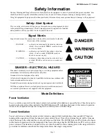
Safety Information- - - - - - - - - - - - - - - - - - - - - - - - - - - - - - - - - - - - 3
C, D, I
Mode Definitions - - - - - - - - - - - - - - - - - - - - - - - - - - - - - - - - - - - - 3
C
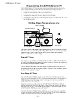
Programming the SUPER-Selector PT - - - - - - - - - - - - - - - - - - - - - - - - - - 4
C
Setting Stage Temperatures - - - - - - - - - - - - - - - - - - - - - - - - - - - - - - - 4
C
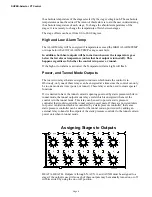
Assigning Stages to Outputs - - - - - - - - - - - - - - - - - - - - - - - - - - - - - - - 6
C
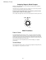
Assigning Stages to Mode Changes- - - - - - - - - - - - - - - - - - - - - - - - - - - - 8
C
Mode Transitions - - - - - - - - - - - - - - - - - - - - - - - - - - - - - - - - - - - - 8
C
Unlabeled Master Selector Position- - - - - - - - - - - - - - - - - - - - - - - - - - - - 9
C
Alarm Output, Powered Inlets - - - - - - - - - - - - - - - - - - - - - - - - - - - - - - 11
C
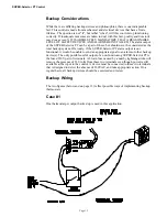
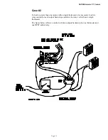
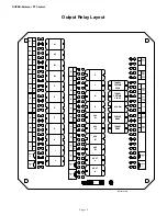
Wiring the System - - - - - - - - - - - - - - - - - - - - - - - - - - - - - - - - - - - - 11
I
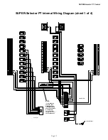
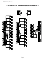
Internal Wiring Diagrams - - - - - - - - - - - - - - - - - - - - - - - - - - - - - - - - 15
I
SUPER-Selector PT Control: Part No. 40866 and 40866C - - - - - - - - - - - - - - - - - 19
I
*Legend: C = Customer (end user), D = Distributor (sales), I = Installer