

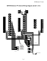
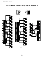


SUPER-Selector
‘
PT Control
Page 19
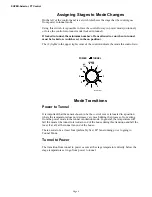
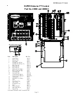
Item
Description
Part No.
1
Control Box
34930
2
Bottom Plate
35448
3
Front Plate
33922
4
Extruded Wear Strip
36512-1
Extruded Wear Strip (4’)
36512-2
5
Relay Bracket
35446-1
6
Relay Bracket
35446-2
6A
Relay Bracket
35446-3
7
Bottom (short) Bridge
33924
8
Bottom (long) Bridge
33927
9
Terminal Strip
34925
10
Terminal Strip
34925-4
11
Circuit Board (40866)
34928PT
Circuit Board (40866C)
34928PTC
12
Transformer
34743
13
P&B SPST 12V Relay
35444
14
MOV
14063-1
15
Slow Blow Fuse
20472
16
Fuse Holder
24431
17
PC Board Cover
34854
18
Knob
35877
19
Corner Bracket
29013-3
20
Sheet Edge Insert
29878
21
Copper Lug
28822
Not Shown Thermistor Probe Assembly 29968
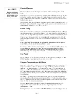
SUPER-Selector
PT
Part No. 40866
0
+
++
OFF
H1
H2
ON
HEA T A
OFF
H1
H2
ON
HEA T B
OPEN
OFF
TUNNEL CURTAIN
LOCKED
IN TUN.
1
2
3
4
5
6
7
8
9
NO
TUN.
1
2
3
4
5
6
7
8
9
OFF
ON
A (2 HP)
1
2
3
4
5
6
7
8
9
OFF
ON
B (2 HP)
1
2
3
4
5
6
7
8
9
OFF
ON
C
1
2
3
4
5
6
7
8
9
OFF
ON
D
1
2
3
4
5
6
7
8
9
OFF
ON
E
1
2
3
4
5
6
7
8
9
OFF
ON
F
1
2
3
4
5
6
7
8
9
OFF
ON
G
1
2
3
4
5
6
7
8
9
OFF
ON
H
1
2
3
4
5
6
7
8
9
OFF
ON
I
1
2
3
4
5
6
7
8
9
OFF
ON
J
AUX- A
(2 HP)
AUX- B (2 HP)
K
L
M
N
SET
POINT
READ SENSOR
FAILED
SENSOR
CHORE-TIME EQUIPMENT
P.O. BOX 2000 - MILFORD, INDIANA 46542-2000
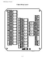
OUTPUTS
ARE
OFF
IN
TUNNEL
SET
POWER
OUTPUTS
ARE
OFF
IN
TUNNEL
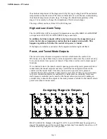
1
2
3
4
5
6
7
8
GREEN - NORMAL
RED - EDIT
ON TIME
OFF TIME
STAGE #1
TIMER
H1
H 2
1
2
3
4
5
6
7
8
9
10
SET
POINT
POWER
TUNNEL
CONTROL SENSOR
AUTO
TEMP
ALARM
ON TIME
OFF TIME
AUX
STAGE #1 TIMER
OFFSETS
TEMPERATURES
ST AGES
HIGH ALARM TEMP
LOW ALARM TEMP
6
7
8
9
H1
H2
1
2
10
4
5
3
®
1
2
3
4
5
OFF
ON
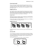
ELECTROCUTION
HAZARD!
Do not open this con-
trol box until electrical
power is disconnected
at circuit breakers.
DANGER
1
2
3
OFF
ON
CLOSE
1
2
3
OFF
ON
1
2
3
4
5
OFF
ON
1
2
3
4
5
OFF
ON
1
2
3
4
5
OFF
ON
Label Part No.
2529-650
1 0
1 0
1 0
1 0
1 0
1 0
1 0
1 0
1 0
1 0
10
20
19
14
SIGNAL TRANSFORMER
500 BAYVIEW AVE.. INWOOD, N.Y. 11696 U.S.A.
6
6
12
5
C9346
7
8
10
9
7
C9346
8
10
9
DP-241-6-12
SIGNAL TRANSFORMER
500 BAYVIEW AVE.. INWOOD, N.Y. 11696 U.S.A.
DP-241-6-12
9
13
25
11
8
2
7
1
15
16
4
21
17
18
3
MV1532-3 1/98
VIEW: UPPER LEFT SIDE OF CONTROL
6
6A
10
SUPER-Selector PT Control
Part No. 40866 and 40866C