


SUPER-Selector
‘
PT Control
Page 6
the absolute temperature of the stage selected by the stage setting knob. These absolute
temperatures cannot be edited. The intent of this feature is to aid the user in determining
the absolute temperature of each stage. To change the absolute temperatures of the
stages, it is necessary to change the temperature offsets between stages.
The stage offsets can be set from 0.0 to 200.0 degrees.
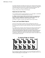
High and Low Alarm Temp
The ALARM relay will be energized if temperatures exceed the HIGH ALARM TEMP
or drops below the LOW ALARM TEMP or any sensor fails.
In addition, both heat outputs will be turned on whenever the temperature goes
below the low alarm temperature (unless that heat output is turned off). This
happens regardless of whether the control is in power or tunnel.
If the high or low alarm is activated, the Temperature Alarm Light will flash.
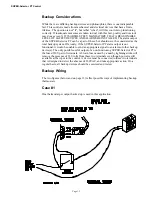
Power, and Tunnel Mode Outputs
There are two relays that are energized to indicate which mode the control is in.
Obviously, only one of these relays can be energized at a time since the control can only
be in one mode at a time (power, or tunnel). These relays can be used to create special
functions.
If it is desired to have the tunnel curtain’s opening governed by static pressure while in
tunnel mode, the tunnel output mode relay exists which is energized whenever the
control is in the tunnel mode. This relay can be used to power a static pressure
controller that would control the tunnel curtain power units. If there are powered inlets
for power ventilation which are controlled by a static pressure controller, that same
static pressure controller can be used for the tunnel curtain power unit by adding an
external relay to transfer the outputs of the static pressure controller to the tunnel curtain
power unit when in tunnel mode.
MV1041-18 3/95
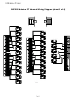
2
3
ON
OFF
1
E
6
5
4
9
10
8
7
3
2
ON
OFF
1
D
5
6
4
8
9
10
7
3
2
ON
OFF
1
C
5
6
4
8
10
9
7
2
3
ON
OFF
1
J
6
5
4
9
10
8
7
3
2
ON
OFF
1
I
5
6
4
8
9
10
7
3
2
ON
OFF
1
H
5
6
4
8
10
9
7
3
2
ON
OFF
B
1
(2 HP)
5
6
4
8
10
9
7
2
3
A
ON
OFF
1
(2 HP)
5
6
4
8
9
10
7
3
2
ON
OFF
1
G
5
6
4
8
10
9
7
3
2
ON
OFF
1
F
6
5
4
8
9
10
7
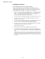
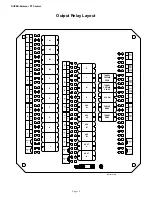
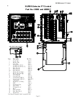
Assigning Stages to Outputs
HEAT A, HEAT B, Outputs A through N, AUX A, and AUX B must be assigned to a
stage if the output is used. Also each of these outputs may be manually turned on or off
with its switch by using the on or off position.