7
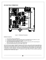
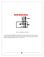
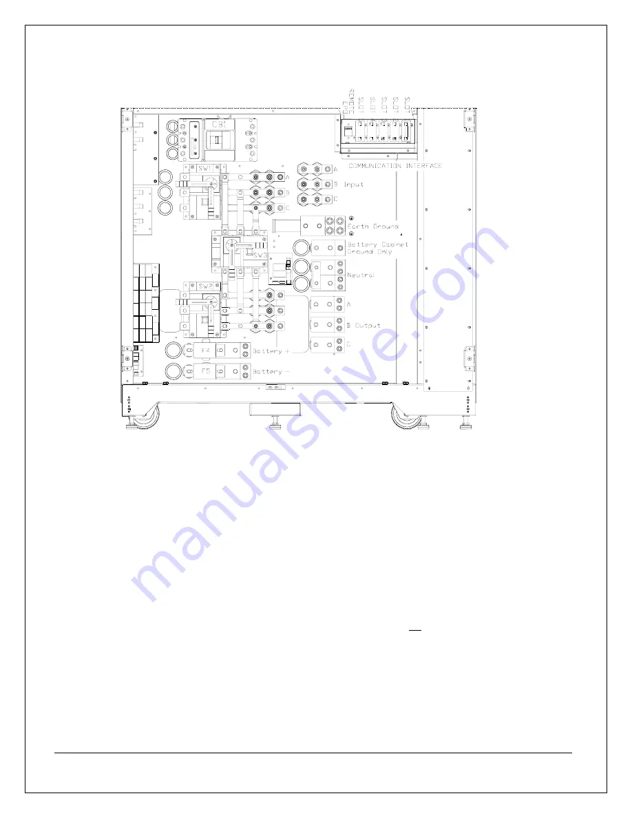
UPS ELECTRICAL TERMINATIONS
Electrical connections
1. Connect the ground wire to the GND terminal.
2. For dual input connect the MAIN AC wires to the INPUT A,B,C, and BY-PASS AC wires to BY-PASS A, B ,C, and N
3. For single input the mains input and bypass will be supplied with jumpers between them.
4. Connect the output AC wires to the output A,B,C, and N
5. Connect the optional battery cabinet positive (+) terminal to the positive (+) terminal in the UPS. Connect the optional
battery cabinet positive (-) terminal to the positive (-) terminal in the UPS.
6. Connect the external battery cabinet ground to the BATT GND terminal.
Note: This UPS may be considered a separately derived source. If this is the case, a jumper will be provided and connected between
ground and the neutral terminations. Therefore, in this configuration an input neutral will not be required. The BY-PASS is phase
rotation sensitive. Clockwise phase rotation is required for the input and bypass. The neutral requirements for the By-Pass input are
solely dependent on the load requirements. If the load requires a Neutral then the Bypass must be supplied with a neutral regardless
of a single input or dual input configuration. This neutral should be sized for three phase unbalanced load conditions. Therefore it is
recommended that the neutral be sized for at least 1.7 times that of the phase conductors. If there is a question concerning this
option, please contact Chloride technical support.
Figure 5 – UPS Electrical Terminations
Содержание CP3150 Series
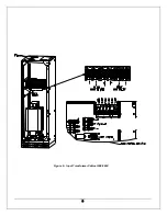
Страница 17: ...8 Figure 6 Input Transformer Cabinet 208 480V ...
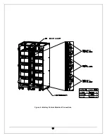
Страница 19: ...10 Figure 8 Battery Cabinet Electrical Connections ...
Страница 51: ...42 INDUSTRIAL CONTACT CARD Figure 22 Industrial Contact Card and Bracket The contacts are rated at 120VAC 2A ...
Страница 61: ...52 Illustration A ...
Страница 62: ...53 Illustration B ...
Страница 63: ...54 BATTERY CABINET TOP DIMENSIONS Illustration C ...

