


Chapter 2
Components Identification
40
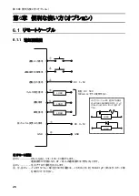
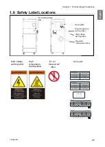
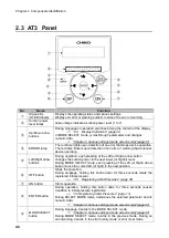
2.3
AT3
Panel
No.
Name
Function
①
Organic EL
(OLED) display
Displays the operating status and various settings.
Displays an error or warning number in case of an error or warning.
②
Suction power
level lamps
Green lamps indicate a suction power level (1 to 7).
③
Up/Down arrow
buttons
During stoppage or operation, switches among the content of the display.
Display Indications” (page 41)
In MODE SELECT mode, cycles through parameters and changes
numeric data.
“Chapter 4 Various settings (mode select mode)”(page 47)
④
ERROR lamp
The red lamp lights upon detection of an error that stops device operation.
The red lamp flickers upon detection of an error or warning that continues
device operation.
⑤
Left/Right arrow
buttons
During operation, each pressing of the Left (or Right) arrow button
changes the suction power to the next lower (or higher) level.
During MODE SELECT mode, each pressing of the Left (or Right) arrow
button moves the cursor left (or right) to the next position.
⑥
OFF button
Stops the operation.
During stoppage, holding this button down for three seconds clears the
registered initial pressure.
Registering Initial Pressures” (page 45)
⑦
ON button
Starts operation.
⑧
ENTER button
During operation, holding this button down for three seconds causes
transition to initial pressure registration.
“3.3 Registering Initial Pressures” (page 13)
During SELECT MODE mode, determines the selected parameter and its
numeric data.
“Chapter 4 Various settings (mode select mode)”(page 47)
⑨
MODE SELECT
button
During stoppage, transits to the MODE SELECT mode.
“Chapter 4 Various settings (mode select mode)”(page 47)
During MODE SELECT mode, returns to the previous mode. During an
error/warning, transits to the error history mode or error clear mode.
①
②
④
⑥
③
③
⑤
⑦
⑤
⑨
⑧
Содержание CMP-2500AT3-A
Страница 3: ......
Страница 6: ...2 6 1 2 28 6 1 3 29 6 2 29 6 2 1 RS485 29 6 2 2 29 7 30 7 1 30 7 2 30 7 3 31 7 3 1 CMP 2500AT3 A 31...
Страница 7: ...1 CMN209 006 3 1 1 1 1 2 10 60 80 1 3 0 40 80 100 1 000...
Страница 8: ...1 4 1 4 2 OFF NV63 SVF 3P 30A 1 5...
Страница 10: ...2 6 2 2 1 4 HEPA V1 1 1 1 1 AWG14 2 08...
Страница 11: ...2 CMN209 006 7 2 2 2 2 1 CMP 2500 AT3 A V1 AT3 BOX HEPA V1...
Страница 12: ...2 8 2 3 AT3 EL OLED No 1 7 2 4 9 4 15 1 1 1 1 OFF 3 3 14 ON ENTER 3 3 3 14 4 15 MODE SELECT 4 15...
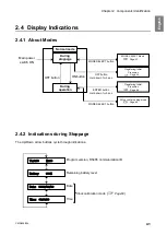
Страница 13: ...2 CMN209 006 9 2 4 2 4 1 2 4 2 ON OFF 15 14 ENTER 3 ON 14 OFF 3 16 Ver ID Battery Date Time RS485 17...
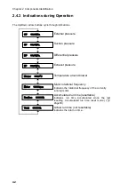
Страница 14: ...2 10 2 4 3 OP kPa SP kPa DP kPa EP kPa Blower Motor rpm Runtime h 17 Total h...
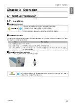
Страница 15: ...3 CMN209 006 11 3 3 1 3 1 1 0 40 80 RH...
Страница 16: ...3 12 3 1 2 200 230V 1 BOX 2 3...
Страница 17: ...3 CMN209 006 13 1 2 8 3 2 1 RS485 ID 2 AT3 ON 3 4 1 7 3 ON OFF 3 30 ON OFF Ver ID...
Страница 23: ...5 CMN209 006 19 5 OFF 2...
Страница 24: ...5 20 5 1 WARN2 1 5 1 1 1 1 2 2 3 4 5 2...
Страница 25: ...5 CMN209 006 21 5 1 2 1 1 1 2 2 2 3 4 1 5 6 2...
Страница 26: ...5 22 5 1 3 V1 1 4 2 3 4 5 2 1 1 1 1...
Страница 29: ...5 CMN209 006 25 5 4 EL 1 2 3 4 1 4 30 1 1 5 1 20 5 1 20 5 1 20 5 1 20...
Страница 30: ...6 26 6 6 1 6 1 1 ON AT 33 0 1 F DC 50V 100mA GND DC 1 5V 33 0 1 F LOAD LOAD DC 0 5V GND LOAD LOAD LOAD...
Страница 31: ...6 CMN209 006 27 1 5V 0 2V B C ON HIGH LOW OFF LOW HI Z LOW DC 1 2...
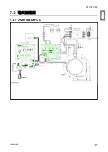
Страница 35: ...7 CMN209 006 31 7 3 7 3 1 CMP 2500AT3 A...
Страница 36: ...32 12 7 2 7 2 30...
Страница 68: ...Chapter 7 Appendix 64 7 3 Electrical Diagram 7 3 1 CMP 2500AT3 A Internal terminal...


