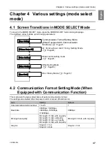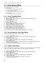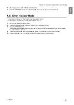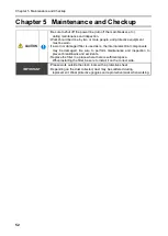
Chapter 4
Various settings (mode select mode)
48
1.
Move to the MODE SELECT mode.
2.
Press the Up/Down arrow buttons to move to the communication format setting mode
(“Com Setting”).
3.
Press the ENTER button.
The communication station number check screen appears, showing the current settings.
4.
Press the Up/ Down arrow buttons to move to the item you want to set.
5.
Press the ENTER button.
The setting screen appears.
6.
Press the Up/Down arrow buttons to select the desired setting.
7.
Press the ENTER button to determine the setting.
8.
To exit this mode, press the MODE SELECT button to return to normal mode.
4.3
Air Volume-Down Alert Timing Setting Mode
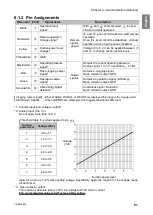
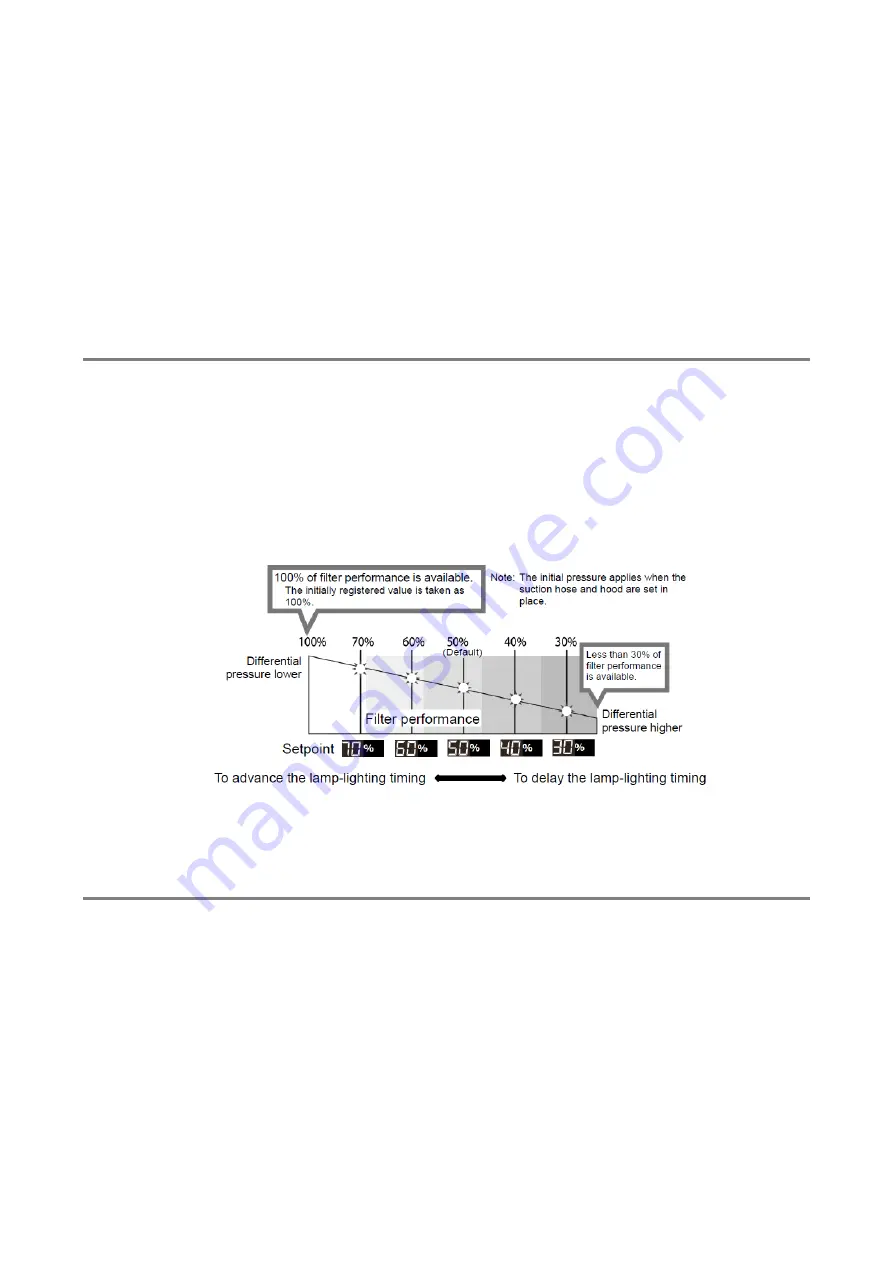
This mode allows for changing the timing for displaying an air volume-down warning (WARN4) as desired.
1.
Move to the MODE SELECT mode.
2.
Press the Up/Down arrow buttons to move to the air volume-down alert timing setting mode
(“Volume Down ST”).
3.
Press the ENTER button.
The current setting appears.
The default is 50%, displayed as “3: Down to 50%”.
4.
Press the Up/Down arrow buttons to select a timing between 30 to 70%.
A lower setting causes the air volume-down alert to occur later, and vice versa.
5.
Press the ENTER button to determine the setting.
6.
To exit this mode, press the MODE SELECT button to return to normal mode.
4.4
Pulse control setting mode
Sets Pulse control interval time and AUTO enable/disable.
■
Interval time
1.
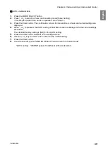
Press the MODE SELECT button.
2.
Press
↑
or
↓
to switch to Pulse control setting mode [Pulse Setting].
(
This step is omitted if the unit is in operation. Go to Step 3.
)
3.
Press the Enter button. The confirmation screen for interval time is shown and current settings are
displayed.
The standard factory setting is 15 minutes.
4.
Press the Enter button. Switches to the settings screen.
5.
Press
←
or
→
to move the 3-digit cursor. Press
↑
or
↓
to change value.
6.
Press the Enter button to set value.
7.
To exit this mode, press the MODE SELECT button to return to normal mode.
Содержание CMP-2500AT3-A
Страница 3: ......
Страница 6: ...2 6 1 2 28 6 1 3 29 6 2 29 6 2 1 RS485 29 6 2 2 29 7 30 7 1 30 7 2 30 7 3 31 7 3 1 CMP 2500AT3 A 31...
Страница 7: ...1 CMN209 006 3 1 1 1 1 2 10 60 80 1 3 0 40 80 100 1 000...
Страница 8: ...1 4 1 4 2 OFF NV63 SVF 3P 30A 1 5...
Страница 10: ...2 6 2 2 1 4 HEPA V1 1 1 1 1 AWG14 2 08...
Страница 11: ...2 CMN209 006 7 2 2 2 2 1 CMP 2500 AT3 A V1 AT3 BOX HEPA V1...
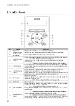
Страница 12: ...2 8 2 3 AT3 EL OLED No 1 7 2 4 9 4 15 1 1 1 1 OFF 3 3 14 ON ENTER 3 3 3 14 4 15 MODE SELECT 4 15...
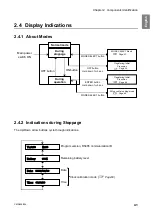
Страница 13: ...2 CMN209 006 9 2 4 2 4 1 2 4 2 ON OFF 15 14 ENTER 3 ON 14 OFF 3 16 Ver ID Battery Date Time RS485 17...
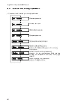
Страница 14: ...2 10 2 4 3 OP kPa SP kPa DP kPa EP kPa Blower Motor rpm Runtime h 17 Total h...
Страница 15: ...3 CMN209 006 11 3 3 1 3 1 1 0 40 80 RH...
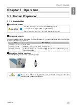
Страница 16: ...3 12 3 1 2 200 230V 1 BOX 2 3...
Страница 17: ...3 CMN209 006 13 1 2 8 3 2 1 RS485 ID 2 AT3 ON 3 4 1 7 3 ON OFF 3 30 ON OFF Ver ID...
Страница 23: ...5 CMN209 006 19 5 OFF 2...
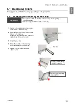
Страница 24: ...5 20 5 1 WARN2 1 5 1 1 1 1 2 2 3 4 5 2...
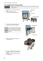
Страница 25: ...5 CMN209 006 21 5 1 2 1 1 1 2 2 2 3 4 1 5 6 2...
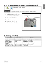
Страница 26: ...5 22 5 1 3 V1 1 4 2 3 4 5 2 1 1 1 1...
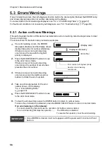
Страница 29: ...5 CMN209 006 25 5 4 EL 1 2 3 4 1 4 30 1 1 5 1 20 5 1 20 5 1 20 5 1 20...
Страница 30: ...6 26 6 6 1 6 1 1 ON AT 33 0 1 F DC 50V 100mA GND DC 1 5V 33 0 1 F LOAD LOAD DC 0 5V GND LOAD LOAD LOAD...
Страница 31: ...6 CMN209 006 27 1 5V 0 2V B C ON HIGH LOW OFF LOW HI Z LOW DC 1 2...
Страница 35: ...7 CMN209 006 31 7 3 7 3 1 CMP 2500AT3 A...
Страница 36: ...32 12 7 2 7 2 30...
Страница 68: ...Chapter 7 Appendix 64 7 3 Electrical Diagram 7 3 1 CMP 2500AT3 A Internal terminal...

