Chapter 1
Product Usage Precautions
CMN209-004
35
E
ng
lis
h
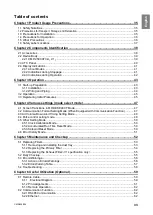
Chapter 1
Product Usage Precautions
1.1
Safety Notations
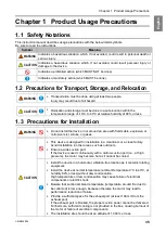
This instruction manual describes usage precautions with the below listed symbols.
Be sure to read the instructions.
Symbol
Meaning
WARNING
Indicates a hazardous situation which, if not avoided, could result in personal death or
serious injury.
CAUTION
Indicates a hazardous situation which, if not avoided, could result personal injury or
damage to the device.
Indicates a prohibited action (which MUST NOT be done).
Indicates a mandatory action (which MUST be done).
1.2
Precautions for Transport, Storage, and Relocation
WARNING
•
Transportation must be done using at least two people.
Injury may result due to fall hazard.
CAUTION
•
Relocation and storage must be done in a safe location within the
temperature range of -10°C to 60°C at relative humidity of 80% or less.
1.3
Precautions for Installation
WARNING
•
Do not install the device in or around an area with flammable, explosive, or
corrosive mist, smoke, or gases.
CAUTION
•
This device is designed for installation in a cleanroom or a clean factory.
Avoid installation in other areas, such as outdoors.
•
Ensure a wide suction port.
If the device is used continuously with a narrow suction port (i.e., at high
pressure), the motor may become hot as it cannot be cooled.
•
Install the device in a horizontal, vibration-free location as it contains rotating
equipment.
•
Install the device at normal temperature (ambient temperature 0°C to 40°C, at
humidity 80% or less) without dew condensation.
High temperature or dew condensation may cause failure of electrical
components or electric shock.
•
Beware that suction ambient temperature (temperature around the dust to
be collected) is low enough, because otherwise the motor may lead to
performance reduction or failure.
•
Provide a sufficient space for the exhaust port (at least 100 mm from the
exhaust port).
If the exhaust port is blocked, the proper suction power cannot be delivered.
Furthermore, sufficient cooling is not provided in the box, causing burnout of
the motor or failure of electrical components.
•
The installation site should be at an altitude of 1,000 m or less.
Содержание CMP-2500AT3-A
Страница 3: ......
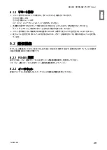
Страница 6: ...2 6 1 2 28 6 1 3 29 6 2 29 6 2 1 RS485 29 6 2 2 29 7 30 7 1 30 7 2 30 7 3 31 7 3 1 CMP 2500AT3 A 31...
Страница 7: ...1 CMN209 006 3 1 1 1 1 2 10 60 80 1 3 0 40 80 100 1 000...
Страница 8: ...1 4 1 4 2 OFF NV63 SVF 3P 30A 1 5...
Страница 10: ...2 6 2 2 1 4 HEPA V1 1 1 1 1 AWG14 2 08...
Страница 11: ...2 CMN209 006 7 2 2 2 2 1 CMP 2500 AT3 A V1 AT3 BOX HEPA V1...
Страница 12: ...2 8 2 3 AT3 EL OLED No 1 7 2 4 9 4 15 1 1 1 1 OFF 3 3 14 ON ENTER 3 3 3 14 4 15 MODE SELECT 4 15...
Страница 13: ...2 CMN209 006 9 2 4 2 4 1 2 4 2 ON OFF 15 14 ENTER 3 ON 14 OFF 3 16 Ver ID Battery Date Time RS485 17...
Страница 14: ...2 10 2 4 3 OP kPa SP kPa DP kPa EP kPa Blower Motor rpm Runtime h 17 Total h...
Страница 15: ...3 CMN209 006 11 3 3 1 3 1 1 0 40 80 RH...
Страница 16: ...3 12 3 1 2 200 230V 1 BOX 2 3...
Страница 17: ...3 CMN209 006 13 1 2 8 3 2 1 RS485 ID 2 AT3 ON 3 4 1 7 3 ON OFF 3 30 ON OFF Ver ID...
Страница 23: ...5 CMN209 006 19 5 OFF 2...
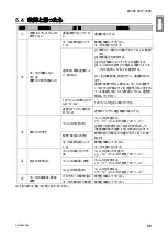
Страница 24: ...5 20 5 1 WARN2 1 5 1 1 1 1 2 2 3 4 5 2...
Страница 25: ...5 CMN209 006 21 5 1 2 1 1 1 2 2 2 3 4 1 5 6 2...
Страница 26: ...5 22 5 1 3 V1 1 4 2 3 4 5 2 1 1 1 1...
Страница 29: ...5 CMN209 006 25 5 4 EL 1 2 3 4 1 4 30 1 1 5 1 20 5 1 20 5 1 20 5 1 20...
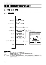
Страница 30: ...6 26 6 6 1 6 1 1 ON AT 33 0 1 F DC 50V 100mA GND DC 1 5V 33 0 1 F LOAD LOAD DC 0 5V GND LOAD LOAD LOAD...
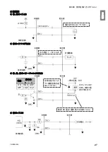
Страница 31: ...6 CMN209 006 27 1 5V 0 2V B C ON HIGH LOW OFF LOW HI Z LOW DC 1 2...
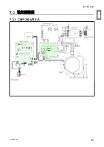
Страница 35: ...7 CMN209 006 31 7 3 7 3 1 CMP 2500AT3 A...
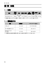
Страница 36: ...32 12 7 2 7 2 30...
Страница 68: ...Chapter 7 Appendix 64 7 3 Electrical Diagram 7 3 1 CMP 2500AT3 A Internal terminal...

