background image

2


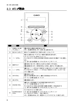
各部の名称


2.3


AT3

パネル


番号


名称


働き


有機

EL

OLED

ディスプレイ


運転状態や各種設定内容を表示します。


エラー・警告発生時は、エラー・警告

No.

を表示します。


能力レベルランプ


能力レベルを緑色のランプで表示します。(レベル

1

7


↑/↓ボタン


停止中、運転中は、ディスプレイの表示内容を切り替えます。


2.4


ディスプレイ表示」(

9

ページ)


モードセレクトモード時は、設定項目の切り替えと設定する数値データを変更し
ます。


「第

4


各種設定(モードセレクトモード)」(

15

ページ)


異常ランプ


運転を停止するエラーが発生したときは、赤色ランプが点灯し、


運転を継続するエラー・警告が発生したときは、赤色ランプが点滅します。


←/→ボタン


運転中は、←(→)ボタンを

1

回押すごとに能力が

1

レベル降下(上昇)します。


モードセレクトモード時は、←(→)ボタンを

1

回押すごとにカーソルが

1

つ左

(右)に移動します。


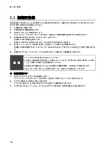
OFF

ボタン


運転を停止します。


停止中に3秒間長押しすると、登録した初期圧をクリアします。


3.3


初期圧登録」(

14

ージ)


ON

ボタン


運転を開始します。


ENTER

ボタン


運転中は、

3

秒間長押しすると初期圧登録に移行します。


3.3


初期圧登録」(

14

ージ)


モードセレクトモード時は、設定項目の選択と数値データを決定します。


「第

4


各種設定(モードセレクトモード)」(

15

ページ)


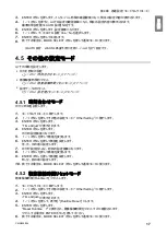
MODE SELECT

ボタン


モードセレクトモードに移行します。


「第

4


各種設定(モードセレクトモード)」(

15

ページ)


モードセレクトモード時は、一つ前に戻ります。


エラー・警告発生時は、エラー履歴モード、エラークリアモードに移行します。


Содержание CMP-2500AT3-A

Страница 1: ...f Instruction Manual hereinafter referred to as this manual and operate it after often reading this manual Please keep this manual carefully to be able to use it at any time CHIKO AIRTEC CO LTD Dust C...

Страница 2: ...tively The CMP Series is an energy saving type clean box that realizes air technology in a compact body Please read this instruction manual thoroughly and handle this CMP Series machine correctly so t...

Страница 3: ......

Страница 4: ...CHIKO AIRTEC CO LTD 562 0012 2 27 24 2 27 24 Hakushima Minoh Osaka 562 0012 Japan TEL 81 072 720 5151 FAX 81 072 720 5133 URL http chiko airtec jp...

Страница 5: ...2500 AT3 A V1 7 2 3 AT3 8 2 4 9 2 4 1 9 2 4 2 9 2 4 3 10 3 11 3 1 11 3 1 1 11 3 1 2 12 3 2 13 3 3 14 4 15 4 1 15 4 2 15 4 3 16 4 4 16 4 5 17 4 5 1 17 4 5 2 17 4 5 3 18 4 6 18 5 19 5 1 20 5 1 1 20 5 1...

Страница 6: ...2 6 1 2 28 6 1 3 29 6 2 29 6 2 1 RS485 29 6 2 2 29 7 30 7 1 30 7 2 30 7 3 31 7 3 1 CMP 2500AT3 A 31...

Страница 7: ...1 CMN209 006 3 1 1 1 1 2 10 60 80 1 3 0 40 80 100 1 000...

Страница 8: ...1 4 1 4 2 OFF NV63 SVF 3P 30A 1 5...

Страница 9: ...age 200 230V Three phase Frequency 50 60Hz Current MASS 135kg SERIAL NUMBER 20XX XX XXXX CHIKO AIRTEC CO LTD MADE IN JAPAN 2 27 24 Hakushima Minoh City Osaka japan 562 0012 CHIKO Electric plaque Model...

Страница 10: ...2 6 2 2 1 4 HEPA V1 1 1 1 1 AWG14 2 08...

Страница 11: ...2 CMN209 006 7 2 2 2 2 1 CMP 2500 AT3 A V1 AT3 BOX HEPA V1...

Страница 12: ...2 8 2 3 AT3 EL OLED No 1 7 2 4 9 4 15 1 1 1 1 OFF 3 3 14 ON ENTER 3 3 3 14 4 15 MODE SELECT 4 15...

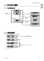
Страница 13: ...2 CMN209 006 9 2 4 2 4 1 2 4 2 ON OFF 15 14 ENTER 3 ON 14 OFF 3 16 Ver ID Battery Date Time RS485 17...

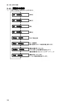
Страница 14: ...2 10 2 4 3 OP kPa SP kPa DP kPa EP kPa Blower Motor rpm Runtime h 17 Total h...

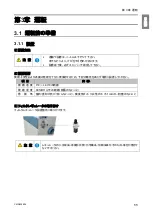
Страница 15: ...3 CMN209 006 11 3 3 1 3 1 1 0 40 80 RH...

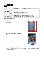
Страница 16: ...3 12 3 1 2 200 230V 1 BOX 2 3...

Страница 17: ...3 CMN209 006 13 1 2 8 3 2 1 RS485 ID 2 AT3 ON 3 4 1 7 3 ON OFF 3 30 ON OFF Ver ID...

Страница 18: ...3 14 3 3 WARN4 1 2 3 ENTER 3 Initial DP Get Y 4 ENTER MODE SELECT 5 1 7 Initial DP Check 6 Initial DP Entry WARN6 OFF 3 1 OFF 3 Initial DP Clr Y 2 ENTER MODE SELECT 3 Initial DP Clr...

Страница 19: ...4 1 MODE SELECT 4 2 1 25 1 9600bps 19200bps 38400bps 57600bps 115200bps 9600bps 8bit 8bit 8bit 9bit 8bit 1 2 1 1 2 Com Setting 3 ENTER 4 Com Setting Volume Down ST Other Setting Error Data 15 16 17 1...

Страница 20: ...ENTER 6 7 ENTER 8 MODE SELECT 4 3 WARN4 1 2 Volume Down ST 3 ENTER 50 3 Down to 50 4 30 70 5 ENTER 6 MODE SELECT 4 4 AUTO 1 2 Pulse Setting 3 ENTER 15 4 ENTER 5 6 ENTER 7 MODE SELECT AUTO 1 2 Pulse S...

Страница 21: ...ENTER 8 MODE SELECT AUTO WARN4 4 5 4 5 1 17 4 5 2 17 4 5 2 18 4 5 1 1 2 Other Setting 3 ENTER Time Adjust 4 ENTER 5 6 ENTER 7 8 9 ENTER 10 MODE SELECT 4 5 2 Runtime 1 2 Other Setting 3 ENTER Time Adj...

Страница 22: ...4 18 4 5 3 AUTO 1 2 Other Setting 3 ENTER Time Adjust 4 Setting Reset 5 ENTER 1 YES ENTER 6 1 START 7 ENTER 4 6 4 OFF 1 2 3 ENTER No 4 4 5 MODE SELECT...

Страница 23: ...5 CMN209 006 19 5 OFF 2...

Страница 24: ...5 20 5 1 WARN2 1 5 1 1 1 1 2 2 3 4 5 2...

Страница 25: ...5 CMN209 006 21 5 1 2 1 1 1 2 2 2 3 4 1 5 6 2...

Страница 26: ...5 22 5 1 3 V1 1 4 2 3 4 5 2 1 1 1 1...

Страница 27: ...5 CMN209 006 23 5 3 No 5 3 2 24 5 4 25 5 3 1 1 No No 2 MODE SELECT No 3 No 4 No 5 5 3 2 24 6 MODE SELECT 7 ENTER MODE SELECT ON WARN6 ERR04 2 ERR04 No 1 WARN4 2 ERR04 ERROR CLEAR Y...

Страница 28: ...5 24 5 3 2 No ERR03 5 4 25 ERR04 5 4 25 ERR06 5 4 25 ERR07 F RAM F RAM ERR08 BCC WARN1 5 4 25 WARN2 5 4 25 WARN3 5 4 25 WARN4 5 4 25 WARN5 5 4 25 WARN6 14...

Страница 29: ...5 CMN209 006 25 5 4 EL 1 2 3 4 1 4 30 1 1 5 1 20 5 1 20 5 1 20 5 1 20...

Страница 30: ...6 26 6 6 1 6 1 1 ON AT 33 0 1 F DC 50V 100mA GND DC 1 5V 33 0 1 F LOAD LOAD DC 0 5V GND LOAD LOAD LOAD...

Страница 31: ...6 CMN209 006 27 1 5V 0 2V B C ON HIGH LOW OFF LOW HI Z LOW DC 1 2...

Страница 32: ...6 28 6 1 2 1 1 2 0 5V GND 1 5V 4 7k 3 NPN 3 ON NPN 3 NPN WARN2 WARN4 WARN5 ERR 1 2 0 5V 5 0V DCV 1 0 6 1 1 2 1 2 1 7 3 1 8 2 3 4 2 4 2 9 5 3 0 3 5 6 3 6 4 1 7 4 2 5 0 4 3 50V 100mA 1 2...

Страница 33: ...6 CMN209 006 29 6 1 3 ON OFF ON OFF 6 1 2 28 ON OFF 6 1 2 ON OFF 6 2 RS 485 RS EN ON OFF 6 2 1 RS485 4 2 4 2 15 6 2 2...

Страница 34: ...7 30 7 7 1 1 CMP 2500AT3 A V1 2800W 200V 230V 16A 50 60Hz 30 min 5 50kPa 65 69dB 135 0kg 1 1m A dB 7 2 1 CMP 2500AT3 A V1 6 12 CS 170 500 63P R 6 12 CHF 3517 30 HEPA V1 6 12 HEP 5040 80 1...

Страница 35: ...7 CMN209 006 31 7 3 7 3 1 CMP 2500AT3 A...

Страница 36: ...32 12 7 2 7 2 30...

Страница 37: ...47 4 1 Screen Transitions in MODE SELECT Mode 47 4 2 Communication Format Setting Mode When Equipped with Communication Function 47 4 3 Air Volume Down Alert Timing Setting Mode 48 4 4 Pulse control...

Страница 38: ...34 Chapter 7 Appendix 63 7 1 Specifications 63 7 2 Consumables List 63 7 3 Electrical Diagram 64 7 3 1 CMP 2500AT3 A 64...

Страница 39: ...explosive or corrosive mist smoke or gases CAUTION This device is designed for installation in a cleanroom or a clean factory Avoid installation in other areas such as outdoors Ensure a wide suction p...

Страница 40: ...o suck dry dust without potential dust explosion Be sure to connect the ground wire CAUTION Do not move the device while in operation Use the device in locations of pollution degree II Use a power sup...

Страница 41: ...ector CMP 2500AT3 A V1 Voltage 200 230V Three phase Frequency 50 60Hz Current MASS 135kg SERIAL NUMBER 20XX XX XXXX CHIKO AIRTEC CO LTD MADE IN JAPAN 2 27 24 Hakushima Minoh City Osaka japan 562 0012...

Страница 42: ...HEPA filter Cleans exhaust V1 specification only 1 Inverter cooling intake exhaust filter Protects electric parts from dust 1 Blower cooling filter Clean the cooling intake air to the blower 1 Instru...

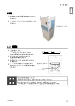
Страница 43: ...t Communication board sold separately installed here Filter regulator installation point Filter regulator included installed here Suction port Connects a suction duct Primary filter chamber Houses the...

Страница 44: ...ng of the Left or Right arrow button changes the suction power to the next lower or higher level During MODE SELECT mode each pressing of the Left or Right arrow button moves the cursor left or right...

Страница 45: ...g operation ON button OFF button MODE SELECT Mode Page 47 MODE SELECT button Registering Initial Pressures Page 45 ENTER button Held down for 3 sec Main power switch ON Registering Initial Pressures P...

Страница 46: ...sure Differential pressure Exhaust pressure Blower Temperature around blower Motor rpm Motor rotational frequency Indicates the rotational frequency of the currently running motor Runtime h Accumulate...

Страница 47: ...ty 80 RH or lower without dew condensation Ambient conditions Indoors not exposed to direct sunlight free of corrosive flammable gases oil mist and dust RInstalling the filter regulator Install the fi...

Страница 48: ...e voltage reduction At reduced voltage the device may fail to operate normally resulting in failure The device is powered by three phase supply Acceptable service voltage range is 220 to 230 V 1 Remov...

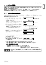
Страница 49: ...l IMPORTANT Switch ON OFF after an interval of 3 or more minutes Repeatedly switching ON OFF within 3 minutes especially within 30seconds may Cause a malfunction 3 3 Registering Initial Pressures Air...

Страница 50: ...ers are replaced except for the exhaust filter after registration of initial pressures If initial pressures are not registered an initial pressure unregistered warning WARN6 appears The registered ini...

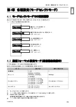
Страница 51: ...itch is turned off and back on Item Setting Default Communication station number 1 to 25 1 Baud rate 9600bps 19200bps 38400bps 57600bps 115200bps 9600bps Bit length and parity Bit length 8 bits with n...

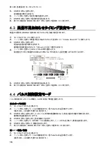
Страница 52: ...setting mode Volume Down ST 3 Press the ENTER button The current setting appears The default is 50 displayed as 3 Down to 50 4 Press the Up Down arrow buttons to select a timing between 30 to 70 A lo...

Страница 53: ...interval time is shown and current settings are displayed 4 When or is pressed the AUTO setting confirmation screen is displayed and the current settings are shown The standard factory setting is NO...

Страница 54: ...return to normal mode 4 5 2 Accumulated Run Time Reset Mode This mode resets the accumulated run time Runtime 1 Move to the MODE SELECT mode 2 Press the Up Down arrow buttons to move to the other sett...

Страница 55: ...ors The error history is cleared by turning off the power switch 1 Move to the MODE SELECT mode 2 Press the Up Down arrow buttons to move to the error history mode 3 Press the ENTER button The display...

Страница 56: ...ter is used as is the internal electrical components may be damaged Be sure to perform maintenance and inspection to prevent breakdowns and accidents Replace the filter in a place where there is suffi...

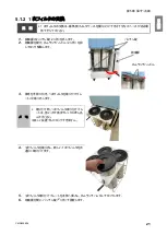
Страница 57: ...r use dispose of the dust in the dust tray 1 Remove the packing locks two places on both sides of the dust tray 2 Open the front door and pull the handle Remove the dust box When removing the dust box...

Страница 58: ...e handle forward and remove the primary filter with its mounting plate Memo When installing the primary filter insert the primary filter mounting plate firmly all the way to the back It can only be lo...

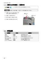
Страница 59: ...ut the exhaust filter 3 Attach a new exhaust filter 4 Reattach the exhaust port lid 5 2 Daily Checkup Check item Frequency Check that Each door Before operation Filter case is completely closed Suctio...

Страница 60: ...Error No 2 Press the MODE SELECT button to move to the error history mode If there are two or more error warning occurrences the number of occurrences precedes the error number 3 If there are two or...

Страница 61: ...operational Contact CHIKO AIRTEC WARN1 Internal temperature high Temperature around the blower is close to the error threshold Flashing Remains operational Follow the remedies for in 5 4 Troubleshoot...

Страница 62: ...he motor may be active Turn off the main power and after 30 minutes resume the operation Primary filter not in place Install the primary filter correctly Latches are unfastened Fastens the latches Low...

Страница 63: ...ns and In case of adding an inductor e g relay install a noise limiter approx 33 0 1 F diode or the like Operation input signal Remote operation change signal Operating pressure signal Filter clogging...

Страница 64: ...2 of maximum rating Pin Pin Connection examples Pins and input Pin analog output Pins and open collector output Pin input State Point B C ON HIGH LOW OFF LOW HI Z Output voltage 1 to 5 V 0 2 V Device...

Страница 65: ...Open collector output NPN Green Operation output signal 3 Outputs an operation signal ON lamp Open collector output NPN Green white Abnormality signal detection 3 Anomalous signal Detection Open colle...

Страница 66: ...evice side during transition to remote operation The current suction power level is stored in memory This means that the previously effective level is stored even if main power is turned off 6 2 Commu...

Страница 67: ...alue is measured with a hose connected to the suction port at a distance of 1m from the device on the A scale 7 2 Consumables List Part name Replacement Intervals 1 CMP 2500AT3 A V1 Primary filter 6 t...

Страница 68: ...Chapter 7 Appendix 64 7 3 Electrical Diagram 7 3 1 CMP 2500AT3 A Internal terminal...

Страница 69: ...RTEC designated sales agent Blemish contamination or other appearance change that may occur during use Replacement of any consumable or accessory or use of any part not designated by CHIKO AIRTEC Fail...

Отзывы: