Cheval CV17116-C5 Скачать руководство пользователя страница 16

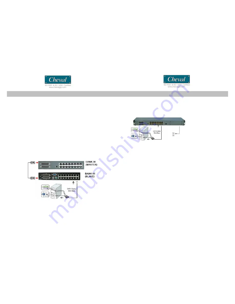
MULTIPLE STAGE INSTALLATION 

Daisy-chaining

For greater expansion capability of your installation, the CAT 5 KVM Switch is designed 
for 15 levels of daisy-chaining. Unlike Cascading, which uses a KVM switch’s CPU ports 
to connect to a slave switch, Daisy-chaining uses dedicated daisy-chain ports. On an 
installation with 15 daisy-chained switches, a system administrator can control up to 
256 computers.

To set up a Multiple Level Installation, do the following;

1. Power off all computers and connected devices.
2. Using CAT 5’s daisy-chain cable set, connect the Chain Out port of the
CV17116-C5(Master  switch)  to  the   Chain  In  port   of   the  CAT  5  KVM  switch  you  are 
installing.
3. Using standard CAT 5E Cable, connect one end of the cable to user Port 1 on the rear 
of the switch. Connect the other end of the cable to the RJ-45 port of the Hamster CAT 5 
Dongle (P/N: Hamster-P / Hamster-U).
4. Connect the keyboard, video and mouse connectors of the Hamster CAT 5 Dongle 
to the computers you are installing.
5. Repeat the above steps for any other additional CAT 5 switches you wish to 
add to the daisy-chain installation.

Note: 

1. The use of CAT 5 cabling allows computers to be placed at a maximum distance of 30m 

(100 feet) away. Performance and VGA quality may degrade beyond this distance.
2. Signal transmission cannot pass through network hubs or switches as data signals are 
not transmitted in packets. Instead patch cables, patch panels and the alike can be 
used to channel data traffic.
3. Only the PS/2 connection is shown on the connection diagram. USB connection is 
similar except that only one USB port is needed for both USB keyboard and USB 
mouse.

Connecting the Power Supply

1. Connect the supplied power cord to the CV17116-C5’s power jack and plug the  
other end of the power cord into an available power outlet.
2. Connect the power adapter to the CAT 5’s power jack and plug the power
adapter into an available power outlet. Do the same for all other connected   
switches.

3. Power up the installation in turn. Power ON each Switch starting with the
CV17116-C5 Master switch, in each case wait for the BANK ID to display before
powering on the next.
4. Perform a manual reset of the “Master” KVM switch by simultaneously pressing
for port 1 and port 2 simultaneously selectors, located on the front panel. All port
LEDs of the “Master” switch will flash green for reset confirmation.
5. Power ON all computers.

Confirmation Procedure

Once all computers are powered on, the switch emulates both mouse and keyboard 
signals on each port allowing your computer to boot normally without errors.

To make sure your daisy-chain installation was successful, do the following:

1. Press 

[SCROLL LOCK] 

twice and enter your 4 digit port ID code (refer to Hot

Keys on p.15 for details). For example: 

[SCROLL LOCK], [SCROLL LOCK], “

0101”

, displays PC1’s screen.

2. Check to see that the keyboard, monitor, and mouse are working normally.
Proceed to do this with all occupied ports to verify that all computers are
connected and responding correctly. If you encounter an error, check your cable
connections for that computer and reboot.

Keyboard / Mouse Reset

If the keyboard and or mouse stop responding, perform a manual reset and reboot.
To reset, simultaneously press both Port 1 and Port 2 selectors simultaneously ,
located on the front panel of the CV17116-C5.

CV17116-C5                                                                                                                                                                                                CV17116-C5

15

16

Содержание CV17116-C5

Страница 1: ...iagrams p6 Installation p7 Panel Controls and Functions p9 Single MULTIPLE Switch Installation p14 OPERATION p16 Hot Key Operation PORT IDENTIFICATI ON p18 Hot key configuration P20 Hot Key summary P2...

Страница 2: ...anagement tool for consolidated server access and control FCC CERTIFICATIONS This equipment has been tested and found to comply with the limits for a Class B digital device pursuant to Part 15 of the...

Страница 3: ...llow you to use designated key commands to switch computers Control multiple computers using a simple hot key sequence from your keyboard Manual Port Selectors Push button selectors allow for convenie...

Страница 4: ...enable your KVM switch to maintain consistent compatibility with the latest devices and computers Firmware upgrades are free for the life of your CV17116 C5 s integrated CAT 5 KVM switch Refer to the...

Страница 5: ...S Item Qty CV17116 C5 1 Power Cord 1 Power Adapter 1 Bracket 2 User Manual 1 Cable Tie 1 Console Cable VGA PS 2 keyboard and mouse 1 Power Adapter External Module 1 Installation hardware kit 1 Please...

Страница 6: ...uage Recall Exit Port Selection OSD Hot Key Push button Computer Port Connector RJ 45 Computer Connections Direct 16 via optional Hamster CAT5 dongle one unit required per PC Computer Connections Dais...

Страница 7: ...s Page Up Page Down to access the required BANK 3 Move the highlight bar to select a connected computer designated by the power symbol and press ENTER Note This series is designed for 15 levels of dai...

Страница 8: ...inch rack systems The sliding brackets feature adjustable positions for rack depths of 22 36 inches Important Information Installing and or removing the Switch module and chassis improperly could void...

Страница 9: ...ist of connected computers controls and function keys as well as symbols that refer to the status of each computer HARDWARE INSTALLATION Please follow these simple steps to install the 17 LCD drawer i...

Страница 10: ...temp Image Setting settings for clock phase gamma and sharpness Position settings for horizontal and vertical positions OSD Menu settings for OSD positions and OSD display timer Language settings for...

Страница 11: ...confirm and exit back to RGB sub menu and press MENU to exit back to the Color sub menu Then please skip to step 6 Color Temp adjusts LCD Color Temp level 9300K Default Color Temp 6500K Default Color...

Страница 12: ...vertical level 0 58 Back returns to the main OSD menu 2 Press the SEL button to enter confirm selection 3 Use the and buttons to adjust the values 4 Press the SEL button to execute the settings in the...

Страница 13: ...lt setting Factory Mode accesses factory setting mode Back returns to the main OSD menu 2 Press the MENU button to enter confirm selection 3 Use the and buttons to adjust the values 4 Press the SEL bu...

Страница 14: ...connect to the Master switch has a BANK ID of 0 The decimal point denotes the Master switch If for example a user selects BANK 2 as the new Master Switch then the BANK ID displays 2 Note a BANK ID suc...

Страница 15: ...computers can be added or removed without shutting down the Switch When hot plugging console ports keyboard monitor and mouse if you experience a problem after removing and adding a new mouse perform...

Страница 16: ...pt that only one USB port is needed for both USB keyboard and USB mouse Connecting the Power Supply 1 Connect the supplied power cord to the CV17116 C5 s power jack and plug the other end of the power...

Отзывы: