Cheval CV17116-C5 Скачать руководство пользователя страница 15

SINGLE KVM SWITCH INSTALLATION

Connecting the Computers

1. Power off all computers.
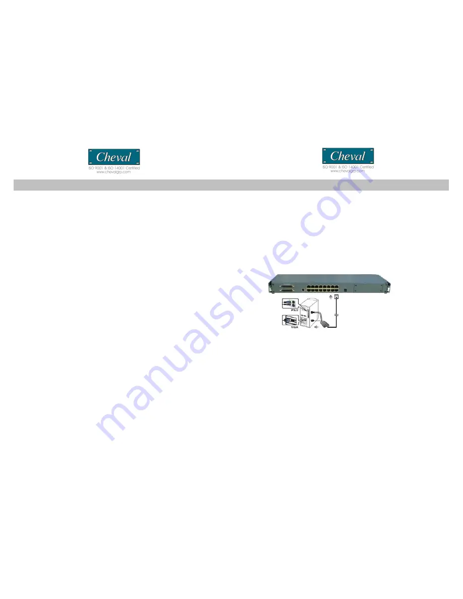
2. Using standard CAT 5E Cable, connect one end of the cable to user Port 1 on the 
rear of the KVM switch. Connect the other end of the cable to the CAT 5 (RJ-45) port of 
the Hamster CAT 5 Dongle (PS2 dongle P/N: Hamster-P ; USB dongle P/N: Hamster-U)
3. Connect the keyboard, mouse and video of the Hamster CAT 5 Dongle to the 
computer you are installing.
4. Repeat steps 2 and 3 for each additional computer you wish to connect.

Note: 

1.The use of CAT 5E cabling allows computers to be placed at a maximum distance of 30m 

(100 feet) away. Performance and VGA quality may degrade beyond this  distance.
2. Signal transmission cannot pass through network hubs or switches as data signals are not 
transmitted in packets. Instead patch cables, patch panels and the alike can be used to channel 
data traffic.
3. For the CV17116-C5 connection diagram, only the PS/2 connection is shown. USB connection 
is similar except that only one USB port is needed for both USB keyboard and USB mouse.

Connecting the Power Supply

1. Connect the power cord to the power jack on the rear of the Switch.
Then plug the other end of the power cord into an available power outlet.

2. Power ON your computers.

CV17116-C5                                                                                                                                                                                                CV17116-C5

OPERATION

Hot Plugging

The CV17116-C5’s integrated features hot plugging where by computers can be added 
or removed without shutting down the Switch. When hot plugging console ports 
(keyboard, monitor, and mouse) if you experience a problem after removing and adding 
a new mouse, perform a 

manual reset by pressing Port 1 and 2 selectors

 of 

CV17116-C5’s front panel. Should the problem continue after performing a system reset, 
restart the computers in question.

Powering Down and Restarting

Powering down the CV17116-C5 and/or attached Switches will not affect the computers 
of your installation. On restarting the CV17116-C5 and/or attached Switches, operator 
control is regained immediately. To replace a Switch, simply do the following:

1. Power down.
2. Remove the cables and plug them into the new switch.
3. Power On.

Access and Control

Controlling your computers with the CV17116-C5’s integrated CAT 5 KVM switch 
couldn’t be easier. The CAT 5 allows you to access the computers using three
simple methods:

Manual Selectors

Hot Keys

OSD (On Screen Display) Menu

Manual Switching

You can directly select any single computer or access any connected Bank

 (↑/↓)

 by 

using the convenient direct-access selector located on the front panel of the CV17116-
C5 Rack Mount Console with integrated CAT 5 KVM Switch. Each port switch has a 
corresponding LED for easy status monitoring. A Green LED indicates current port 
selection (Selected). A Red LED light indicates a port is not selected but the connected 
computer is powered and ready (Online). The CV17116-C5 is also equipped with a 
seven segment LED display for BANK identification when daisy-chaining.

17

14

Содержание CV17116-C5

Страница 1: ...iagrams p6 Installation p7 Panel Controls and Functions p9 Single MULTIPLE Switch Installation p14 OPERATION p16 Hot Key Operation PORT IDENTIFICATI ON p18 Hot key configuration P20 Hot Key summary P2...

Страница 2: ...anagement tool for consolidated server access and control FCC CERTIFICATIONS This equipment has been tested and found to comply with the limits for a Class B digital device pursuant to Part 15 of the...

Страница 3: ...llow you to use designated key commands to switch computers Control multiple computers using a simple hot key sequence from your keyboard Manual Port Selectors Push button selectors allow for convenie...

Страница 4: ...enable your KVM switch to maintain consistent compatibility with the latest devices and computers Firmware upgrades are free for the life of your CV17116 C5 s integrated CAT 5 KVM switch Refer to the...

Страница 5: ...S Item Qty CV17116 C5 1 Power Cord 1 Power Adapter 1 Bracket 2 User Manual 1 Cable Tie 1 Console Cable VGA PS 2 keyboard and mouse 1 Power Adapter External Module 1 Installation hardware kit 1 Please...

Страница 6: ...uage Recall Exit Port Selection OSD Hot Key Push button Computer Port Connector RJ 45 Computer Connections Direct 16 via optional Hamster CAT5 dongle one unit required per PC Computer Connections Dais...

Страница 7: ...s Page Up Page Down to access the required BANK 3 Move the highlight bar to select a connected computer designated by the power symbol and press ENTER Note This series is designed for 15 levels of dai...

Страница 8: ...inch rack systems The sliding brackets feature adjustable positions for rack depths of 22 36 inches Important Information Installing and or removing the Switch module and chassis improperly could void...

Страница 9: ...ist of connected computers controls and function keys as well as symbols that refer to the status of each computer HARDWARE INSTALLATION Please follow these simple steps to install the 17 LCD drawer i...

Страница 10: ...temp Image Setting settings for clock phase gamma and sharpness Position settings for horizontal and vertical positions OSD Menu settings for OSD positions and OSD display timer Language settings for...

Страница 11: ...confirm and exit back to RGB sub menu and press MENU to exit back to the Color sub menu Then please skip to step 6 Color Temp adjusts LCD Color Temp level 9300K Default Color Temp 6500K Default Color...

Страница 12: ...vertical level 0 58 Back returns to the main OSD menu 2 Press the SEL button to enter confirm selection 3 Use the and buttons to adjust the values 4 Press the SEL button to execute the settings in the...

Страница 13: ...lt setting Factory Mode accesses factory setting mode Back returns to the main OSD menu 2 Press the MENU button to enter confirm selection 3 Use the and buttons to adjust the values 4 Press the SEL bu...

Страница 14: ...connect to the Master switch has a BANK ID of 0 The decimal point denotes the Master switch If for example a user selects BANK 2 as the new Master Switch then the BANK ID displays 2 Note a BANK ID suc...

Страница 15: ...computers can be added or removed without shutting down the Switch When hot plugging console ports keyboard monitor and mouse if you experience a problem after removing and adding a new mouse perform...

Страница 16: ...pt that only one USB port is needed for both USB keyboard and USB mouse Connecting the Power Supply 1 Connect the supplied power cord to the CV17116 C5 s power jack and plug the other end of the power...

Отзывы: