cap screw.
Figure 43
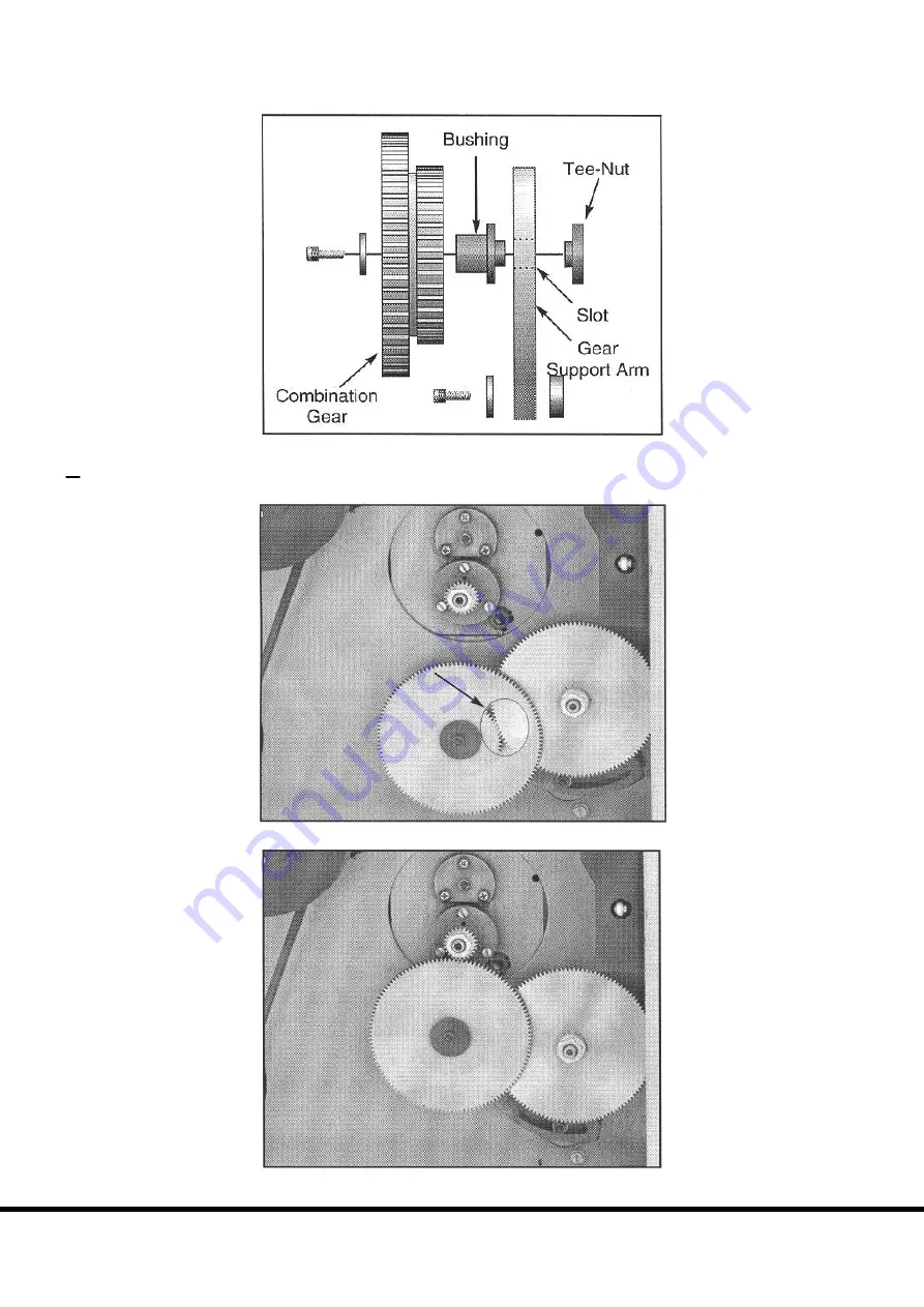
shows the proper sequence. Slide the combination gear along the slot in the support
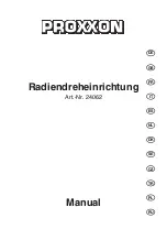
arm until gear C meshes with gear D, as in
Figure 44
, and tighten the cap screw.
Figure 43
. Flats on bushing align slot.
8.
Rotate the support arm until gears B and A are in mesh. Tighten the cap screw at the bottom of the gear
support arm.
Figure 45
shows the gears properly aligned and in mesh.
Figure 44
. Cutaway shows Gear C and D in mesh.
Figure 45
. Gears aligned and in mesh.
Chester UK Model B
28


