


22
Chapter 2. Overview
Backlight Timeout
In order to extend the life of the display a timeout can be set. At the end of the
timeout the display will go dark. Any button press will turn the screen back on. Use the checkbox
to enable or disable the backlight timeout and set the desired timeout using the up/down buttons.
The timeout is in HH:MM:SS format.
Home Button
On most displays the left button under the display can be set to take the user to the
“Home” screen or the “Menu” screen.
Blink highlighted
If this option is enabled, the element the user needs to look at blinks between two
colors to attract attention.
2.4.5.2.1
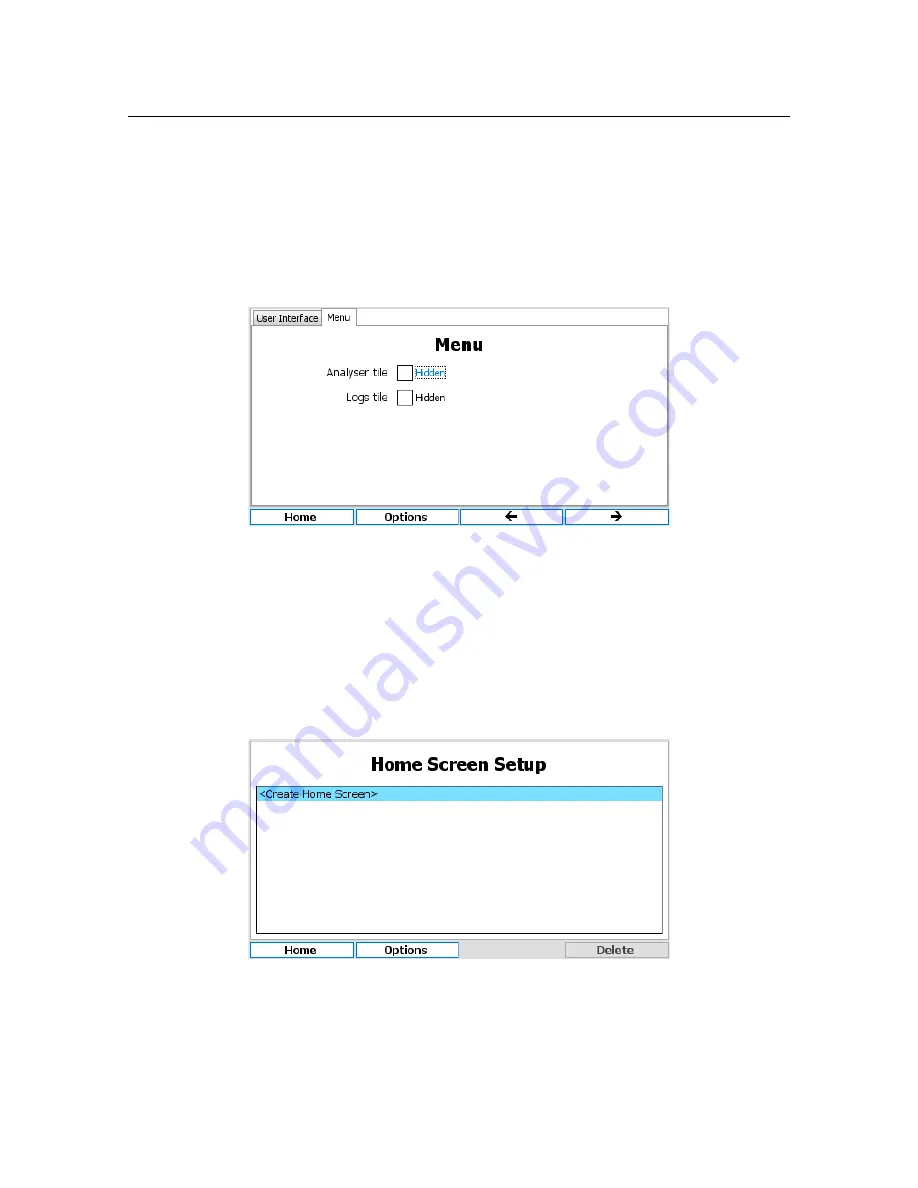
Menu
Analyzer tile
If the checkbox is ticked then the Analyzer tile will be hidden as default on the main
menu.
Logs tile
If the checkbox is ticked then the Logs tile will be hidden as default on the main menu.
2.4.5.3
Home Screens
The HydroAct 4 has the capability to have multiple home screens which give the user options as to
how the display provides information (see section 2.4.3). To set up a new home screen, edit or delete
an existing home screen, select:
Options
→
Setup
→
Home Screen
To delete a home screen highlight the home screen name with the up/down buttons and press
“Delete”. Pressing and holding the “Delete” key will make the “Delete All” function available. A
confirmation message box will appear before all home screens are deleted. To edit the home screen,
again select the name, and press the select button. To create a new home screen, select “Create
Home Screen” and press select.
Содержание HydroAct 4
Страница 1: ...HydroAct 4 User Manual Chemtrac Inc Firmware Version 1 19 November 15 2017...
Страница 8: ......
Страница 9: ...I 2 Overview 11 2 1 Safety Precautions 2 2 Technical Data 2 3 Installation 2 4 Operation Analyzer...
Страница 10: ......
Страница 32: ......
Страница 33: ...II 3 Sensors 35 3 1 PC6 Particle Counter 4 Outputs 55 4 1 Analog Outputs 4 2 Relay Output Options...
Страница 34: ......
Страница 54: ......
Страница 72: ......
Страница 73: ...III 5 Warranty 75 6 Returns 77 6 1 Contact Details Documentation...
Страница 74: ......
Страница 76: ......


