background image

Korg Polysix MIDI Interface

Korg Polysix MIDI Interface

Korg Polysix MIDI Interface

Korg Polysix MIDI Interface  

 P6

 P6

 P6

 P6----M

M

M

M Installation

 Installation

 Installation

 Installation Manual

 Manual

 Manual

 Manual    

8

88

8----427 / v. 1.00

427 / v. 1.00

427 / v. 1.00

427 / v. 1.00


Copyright © 2021 CHD Elektroservis.  All rights reserved.  

No part of this publication may be reproduced in any form without the written permission of CHD Elektroservis.


7

77

7

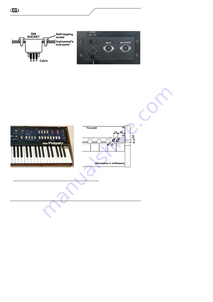
c) It is recommended to label the DIN sockets ("MIDI IN", "MIDI THRU/OUT" for example) with self-adhesive foil 
glued near the sockets (fig. 2.2.5). 

    Fig. 2.2.4

    Fig. 2.2.4

    Fig. 2.2.4

    Fig. 2.2.4    


 Fig. 2.2.5

 Fig. 2.2.5

 Fig. 2.2.5

 Fig. 2.2.5    


2.3

2.3

2.3

2.3     RESET BUTTON AND INDICATION LED INSTALLATION

RESET BUTTON AND INDICATION LED INSTALLATION

RESET BUTTON AND INDICATION LED INSTALLATION

RESET BUTTON AND INDICATION LED INSTALLATION    


There are two control elements on the interface – reset button and indication LED. There are more possible 
ways to install the button and the LED. The button and the LED need not be installed if you prefer to maintain 
the vintage status of the instrument (i.e. if you don’t want to damage the instrument’s panel by drilling). Or you 
can install only the reset button or only the indication LED (see chapter 3.2). Nevertheless having both of them 
installed is more convenient for easier device control. 
 
2.3.1

2.3.1

2.3.1

2.3.1     HOLES FOR

HOLES FOR

HOLES FOR

HOLES FOR RESET BUTTON AND INDICATION LED DRILLING

 RESET BUTTON AND INDICATION LED DRILLING

 RESET BUTTON AND INDICATION LED DRILLING

 RESET BUTTON AND INDICATION LED DRILLING    


a) If you decide to install the LED and the button, the suitable place for them is the right side of the front panel 
of the instrument - above the highest keys (fig. 2.3.1). 

b) Drill one hole with diameter 7 mm (for reset button) and one hole with diameter 6,5 mm (for indication LED) 
to the panel – see fig. 2.3.2. Use sharp drills and work carefully

work carefully

work carefully

work carefully so that the panel is not scratched and other 

parts of the instrument are not damaged during the drilling! 

Fig. 2.3.1

Fig. 2.3.1

Fig. 2.3.1

Fig. 2.3.1    


      Fig. 2.3.2

      Fig. 2.3.2

      Fig. 2.3.2

      Fig. 2.3.2    


c) Clean the edge of the holes with small rasp or tip of bigger drill from both sides of the panel after the holes 
are drilled. 

d) Clean all iron sawdust and raspings from the inside of the instruments

Clean all iron sawdust and raspings from the inside of the instruments

Clean all iron sawdust and raspings from the inside of the instruments

Clean all iron sawdust and raspings from the inside of the instruments, they can cause short circuits or serious 

electrical damage if they are left inside the instrument. Please clean the instrument carefully! 


Содержание 8-427

Страница 1: ...ix Synthesizer Korg Polysix Synthesizer Korg Polysix Synthesizer Model 8 Model 8 Model 8 Model 8 427 427 427 427 Version 1 0 Version 1 0 Version 1 0 Version 1 0 Installation Manual Installation Manual Installation Manual Installation Manual 2021 CHD Elektroservis 2021 CHD Elektroservis 2021 CHD Elektroservis 2021 CHD Elektroservis ...

Страница 2: ...FORMATION 3 1 3 INTERFACE CONNECTION 4 2 2 2 2 INSTALLATION PROCEDURE INSTALLATION PROCEDURE INSTALLATION PROCEDURE INSTALLATION PROCEDURE 5 5 5 5 2 1 THE INSTRUMENT OPENING 5 2 2 MIDI DIN SOCKETS INSTALLATION 5 2 2 1 HOLES FOR MIDI SOCKETS DRILLING 6 2 2 2 MIDI SOCKETS MOUNTING 6 2 3 RESET BUTTON AND INDICATION LED INSTALLATION 7 2 3 1 HOLES FOR RESET BUTTON AND INDICATION LED DRILLING 7 2 3 2 RE...

Страница 3: ...Attention Observe precautions for handling electrosta Attention Observe precautions for handling electrosta Attention Observe precautions for handling electrostatic discharge sensitive devices tic discharge sensitive devices tic discharge sensitive devices tic discharge sensitive devices The producer is not responsible for any eventual mechanical or electrical damage of the Korg The producer is no...

Страница 4: ... 1 3 1 3 1 3 INTERFACE CONNECTION INTERFACE CONNECTION INTERFACE CONNECTION INTERFACE CONNECTION The interface is connected to the KLM 366 and KLM 371 boards of the instrument The following diagrams figs 1 3 1 1 3 2 explain the electrical connection of the interface in the instrument Fig 1 3 1 Fig 1 3 1 Fig 1 3 1 Fig 1 3 1 Connection to the instrument Connection to the instrument Connection to the...

Страница 5: ...w the four screws on the bottom side of the instrument fig 2 1 1 and four screws on the top panel fig 2 1 2 Keep the screws They will be used again after the MIDI kit installation is finished Fig 2 1 1 Fig 2 1 1 Fig 2 1 1 Fig 2 1 1 Fig 2 1 2 Fig 2 1 2 Fig 2 1 2 Fig 2 1 2 b Carefully lift up the instrument top panel and turn it back fig 2 1 3 All instrument s parts and boards needed for the interfa...

Страница 6: ...d sub panel fig 2 2 1 Safely store the serial number plate and two self tapping screws for future usage 1 1 1 1 c Drill two holes with diameter 16 mm and two holes with diameter 2 2 mm to the sub panel of the instrument as shown on fig 2 2 2 Use sharp drills and work carefully work carefully work carefully work carefully so that the panel is not scratched and other parts of the instrument are not ...

Страница 7: ... chapter 3 2 Nevertheless having both of them installed is more convenient for easier device control 2 3 1 2 3 1 2 3 1 2 3 1 HOLES FOR HOLES FOR HOLES FOR HOLES FOR RESET BUTTON AND INDICATION LED DRILLING RESET BUTTON AND INDICATION LED DRILLING RESET BUTTON AND INDICATION LED DRILLING RESET BUTTON AND INDICATION LED DRILLING a If you decide to install the LED and the button the suitable place fo...

Страница 8: ... s panel from the outer side Pull the lock ring of the LED holder over the supplied LED Then insert the LED into the holder from inner side of the instrument s panel and fix it by the overthrust of the ring on the holder fig 2 3 3 2 3 4 b Insert the reset button into 7 mm hole in the instrument s panel from inner side Fix the button to the panel with the nut and spring washer fig 2 3 3 2 3 4 Fig 2...

Страница 9: ...ctor Connector Connector Pad Nr Pad Nr Pad Nr Pad Nr Remark Remark Remark Remark Wire Nr Wire Nr Wire Nr Wire Nr Signal Signal Signal Signal Connector Connector Connector Connector Pad Nr Pad Nr Pad Nr Pad Nr Re Re Re Remark mark mark mark 1 P17 CN12 6 Red signed wire 11 ACKI CN12 17 Unsolder the orig wire 2 P16 CN12 7 12 ACKO CN12 17 To the orig freed wire 3 P15 CN12 8 13 PO13 CN10 5 4 P14 CN12 9...

Страница 10: ... 4 7 Fig 2 4 7 Fig 2 4 7 Fig 2 4 7 e Wires from Nr 13 to Nr 20 of the 20 core ribbon cable are solderd directly to pads 5 to 12 of CN10 connector4 4 4 4 as shown on fig 2 4 7 Solder the wires to these pads directly in parallel manner to original wires leaded to the pads 2 5 2 5 2 5 2 5 16 16 16 16 CORE RIBBON CABLE MOUNTING CORE RIBBON CABLE MOUNTING CORE RIBBON CABLE MOUNTING CORE RIBBON CABLE MO...

Страница 11: ...gnal Connector Connector Connector Connector Pad Nr Pad Nr Pad Nr Pad Nr Remark Remark Remark Remark Wire Nr Wire Nr Wire Nr Wire Nr Signal Signal Signal Signal Connector Connector Connector Connector Pad Nr Pad Nr Pad Nr Pad Nr Remark Remark Remark Remark 1 DB0 CN04 9 Red signed wire 9 FCMO CN17 3 To lead of R51 resistor 2 DB1 CN04 10 10 FCMI CN17 3 To freed pad 3 DB2 CN04 11 11 5V 4 DB3 CN04 12 ...

Страница 12: ...he wires are soldered to some via pads on the board what conforms to the pins of the CN01 connector fig 2 5 10 Fig 2 5 9 Fig 2 5 9 Fig 2 5 9 Fig 2 5 9 Fig 2 5 10 Fig 2 5 10 Fig 2 5 10 Fig 2 5 10 g Solder both Nr 11 and Nr 12 wires of the 16 core ribbon cable to the 5V via pad It conforms to pin 2 of the CN01 connector fig 2 5 10 h Solder both Nr 13 and Nr 14 wires of the 16 core ribbon cable to th...

Страница 13: ... Plug two 3 pin connectors of the MIDI cables to X3 IN and X4 OUT plug heads on the interface board Orientation of the connectors is given by the connector lock so they cannot be plugged reversely but be sure that the connectors are not exchanged MIDI input must be plugged to X3 head and MIDI outputto X4 head fig 2 6 4 f Plug the 4 pin connector of the bunched cables with button and LED to X5 CTRL...

Страница 14: ...top panel to the side boards of the instrument with four original screws fig 2 7 1 and to the bottom plate of the instrument s cover with four original screws fig 2 7 2 This is the reverse procedure of that described in the chapter 2 1 Fig 2 7 1 Fig 2 7 1 Fig 2 7 1 Fig 2 7 1 Fig 2 7 2 Fig 2 7 2 Fig 2 7 2 Fig 2 7 2 The installation of the P6 M MIDI kit is now finished the instrument is ready for us...

Страница 15: ...ig 3 1 1 Fig 3 1 1 Fig 3 1 1 Fig 3 1 2 Fig 3 1 2 Fig 3 1 2 Fig 3 1 2 X4 MIDI OUT 3 2 3 2 3 2 3 2 RESET BUTTON AND INDICATION LED RESET BUTTON AND INDICATION LED RESET BUTTON AND INDICATION LED RESET BUTTON AND INDICATION LED Fig 3 2 1 Fig 3 2 1 Fig 3 2 1 Fig 3 2 1 Installation of the reset button and indication LED isn t necessary as well You don t need to install this bunched cables if you don t ...

Страница 16: ...nt see user manual of the interface Fig 3 2 3 Fig 3 2 3 Fig 3 2 3 Fig 3 2 3 3 3 3 3 3 3 3 3 MEMORY PROTECTION MEMORY PROTECTION MEMORY PROTECTION MEMORY PROTECTION Fig 3 3 1 Fig 3 3 1 Fig 3 3 1 Fig 3 3 1 All user data stored in interface memory can be protected against unwanted rewriting after the memory is filled with your own data The jumper from interface accessory have to be plugged on pin hea...

Отзывы: