8
Ergostyle ™ FX Tables
4 TROUBLESHOOTING
4.2 VISUAL INSPECTION
A. General
Visually inspect the unit. A visual
inspection can, to an experienced Technician,
indicate possible abuse of the unit and
internal
problems.
4.3 GROUND RESISTANCE TEST
A. Voltage Specifications
Models 5820 and 5822 . . . . . . . . . Input: 100-240 VAC
50/60 Hz, 2AA
B. Specification
Maximum Acceptable Resistance: 100 milliohms
C. Equipment Required
Milliohm
Meter
D. Test
Place unit on level work surface.
Place one meter probe on the ground prong of
the Mains Power Cord and the other to any
exposed metal or screw on the unit. See
Figure
4.1.
NOTE:
U.S.A. Power Cord Illustrated.
4.4 LEAKAGE TESTS
Test Voltage Spec . . . . . . . . . . . . . . . . . . . . . . . . . . . . . .1500 V
Conduct all necessary leakage tests as required per
“Chapter 7 Electrical Equipment” of the 1999, or
later, edition of the NFPA (National Fire Protection
Association) “Health Care Facilities” standards.
See Figure 4.2.
NOTE:
The NFPA "Health Care Facilities" standards are specific
to the U.S.A. All other technicians should verify their
country's requirements for these tests.
FIGURE 4.2
FIGURE 4.1
UNIT FAILING DIELECTRIC WITHSTAND AND/OR
LEAKAGE TESTS COULD INDICATE SERIOUS
INTERNAL SYSTEM PROBLEMS.
DO NOT PLACE UNIT BACK INTO SERVICE!
CONTACT FACTORY FOR SERVICE!
DO NOT ATTEMPT TO REPAIR IN THE FIELD!
GROUND PRONG
EXPOSED METAL
Содержание ERGOSTYLE FX 5820
Страница 24: ...Ergostyle FXTables 22 8 SCHEMATICS Block Diagram 1 of 1 ...
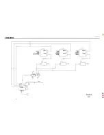
Страница 25: ...Ergostyle FXTables 23 8 SCHEMATICS Pneumatic 1 of 1 ...
Страница 26: ...Ergostyle FXTables 24 8 SCHEMATICS Driver Board 58432 1 of 1 ...
Страница 27: ...Ergostyle FXTables 25 8 SCHEMATICS Control Board 58433 1 of 1 ...
Страница 28: ...Ergostyle FXTables 26 8 SCHEMATICS Daughter Board 58543 1 of 1 ...


