Chassis Plans CPX1-241 Technical Reference
Chapter 1 - Introduction
Page 11
LCD Enhancements
In the CPX family of rugged military grade LCD displays, Chassis Plans starts with Grade A Industrial Quality
LCD panels selected for optical performance, high reliability and long product life cycle. Standard, in order to not
only ruggedize the LCD, but to also enhance the mechanical, optical and EMI properties of the finished unit
Chassis Plans optically bonds a layer of glass to the front of the LCD panel which is coated with an oleophobic
Anti-Reflective (AR) coating. The adhesive is optically clear and refractive index matched to eliminate interface
reflections.
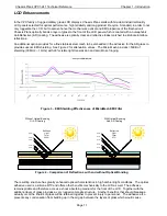
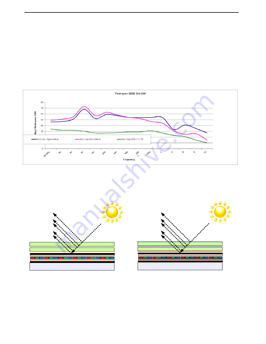
An additional option provides for a fine stainless steel mesh to be embedded in the adhesive for the AR glass to
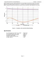
provide superior EMI shielding. See Figure 2 for attenuation values. The Micro Mesh provides >50dB of
shielding (30 MHz – 1 GHz) with 90% visible light transmission and zero Moiré fringing.
Figure 3 – EMI Shielding Effectiveness of MicroMesh EMI Filter
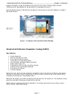
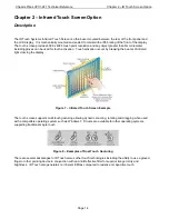
Figure 4 – Comparison of Reflections with and without Optical Bonding
The resulting structure has greatly enhanced optical characteristics in high ambient light conditions. The optical
adhesive used is a silicone RTV and offers other benefits mechanically to the LCD as well. The adhesive
remains pliable and therefore acts as a shock absorbing medium for the front of the LCD. Together with the
additional layer of glass provides a very rugged composite structure. Another benefit is that should breakage
actually occur the shards of glass will be retained together to prevent injury to personnel. The adhesive also
prevents any condensation from building up in the air gap between the layers of glass which would cause
Reflected
Light
Total
22.5%
4.5%
4.5%
4.5%
4.5%
4.5%
Without Optical Bonding
Or AR Coating
Reflected
Light
Total
0.7%
0.3%
With Optical Bonding
And AR Coating
0.1%
0.1%
0.1%
0.1%
Содержание CPX1-241
Страница 2: ...This Page Intentionally Blank ...
Страница 8: ...This Page Intentionally Blank ...
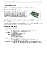
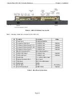
Страница 13: ...Chassis Plans CPX1 241 Technical Reference Chapter 1 Introduction Page 5 Photo 6 I O Connections ...
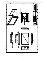
Страница 17: ...Chassis Plans CPX1 241 Technical Reference Chapter 1 Introduction Page 9 Figure 1 CPX1 241 Customer Drawing ...
Страница 28: ...Chassis Plans CPX1 241 Technical Reference Chapter 5 Package Contents Page 20 This Page Intentionally Blank ...
Страница 58: ...Chassis Plans CPX1 241 Technical Reference Appendix B Auto Color Gain Page 50 This Page Intentionally Blank ...
Страница 62: ...Chassis Plans CPX1 241 Technical Reference Appendix E PIP Mix Table Page 54 This Page Intentionally Blank ...
Страница 64: ...Chassis Plans CPX1 241 Technical Reference Appendix E PIP Mix Table Page 56 This Page Intentionally Blank ...
Страница 70: ...Chassis Plans CPX1 241 Technical Reference Appendix F Network Connection Page 62 This Page Intentionally Blank ...
Страница 72: ...Chassis Plans CPX1 241 Technical Reference Appendix G DVI D versus DVI I Page 64 This Page Intentionally Blank ...


