18
17.
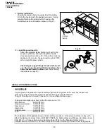
Battery Installation
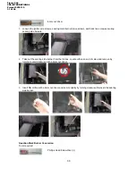
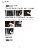
Unscrew the ignition button housing, insert the battery
(II) into the housing with the positive terminal (+) facing
outward. Replace the ignition button housing after
the battery has been installed as shown in Fig. 24.
18.
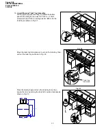
Liquid Propane Hook-Up
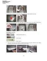
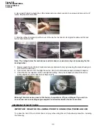
Attach the regulator inside the main grill cart to the
propane cylinder by turning the regulator handle
clockwise as shown in Fig. 25. If the outdoor cooking
appliance is not in use, the gas must be turned “OFF”
at the Liquid Propane cylinder.
Check all gas supply fittings for leaks before each
use. Do not use the grill until all connections have
been checked and do not leak
(see “Leak Testing”
instructions on page 20).
INSTALLATION INSTRUCTIONS
GAS HOOK-UP
Only the pressure regulator and hose assembly supplied with the grill should be used. Any replacement
pressure regulator and hose assembly must be specified by the grill manufacturer.
This grill is configured for Liquid Propane. Do not use a Natural Gas supply.
Total gas consumption (per hour) with all burners set on “HI”:
Main burners 40,000 BTU/Hr.
Searing main burner 12,000 BTU/Hr
Rear burner
13,000 BTU/Hr.
Side burner
12,000 BTU/Hr.
Griddle burner 12,000 BTU/Hr.
Total
89,000 BTU/Hr.
The installation of this appliance must conform with local codes or, in the absence of local codes, with
either the National Fuel Gas Code, ANSI Z223.1/NFPA 54, National Gas and Propane Installation Code,
CSA B149.1, or Propane Storage and Handling Code, B149.2,or the Standard for Recreation
Vehicles,ANSI A119.2/NFPA 1192, and CSA Z240 RV Series, Recreation Vehicle Code, as applicable.
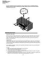
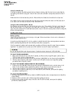
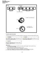
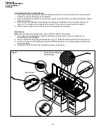
Fig. 25
B
A
Fig. 24
II
Ignition
button
Figure 246
CSA INTERNATIONAL
Project 2078110
19 of 46


