Chamberlain WGO200 Скачать руководство пользователя страница 15

3.5  EMERGENCY BATTERY

Fig. 11

The system can also operate AUTOMATICALLY, i.e. without power
supply coming from the mains supply. By installing a 12V 6,3 Amp.
battery, it will be possible to carry out approx. 30 emergency
operations without power supply.
The battery can be fit in the proper space inside the plastic casing
containing the control unit. The programmer is provided with an
automatic device able to keep the battery charged. Provide for the
connection of the battery to the Fig. 12 terminals complying with the
polarity. Before using the system with only the battery it shall be first
charged for at least 24h.

3.6  KEYSWITCH ASSEMBLY

(Accessories)

Avoid to use simultaneously the transmitter. The switch can operate
the gate according to the set program. The contact is Normally Open
N.O. In case more than one selector or possibly a switch were to be
fitted, carry out parallel connections.

Caution: For a higher force-proof safety, we advise to make
the connection cable pass inside a walled cable duct.

3.7  FLASHING LAMP

Fig. 16

This device is foreseen by all safety EEC norms, and it has to be
installed in a visible position.
Size and light features are in compliance with norms in force.
The device operates at LOW VOLTAGE and is provided with a lamp
holder and a 12V 10W bulb.

Caution: Never exceed this power as there might be the risk
of damaging circuits.

Operation: The intermittent signal comes from the control unit. The
activation starts 2 seconds before each operation. 
The blinking is slow when the gate opens and faster when the gate
closes.

Caution: Firmly fix the device as vibrations may reduce the bulb
lifetime.

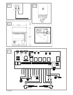
3.8  TRANSMITTER ENCODING

Fig. 13

The PTT-approved, charge-free radio remote control unit
functions with a computer pre-programmed private security
code
. In this way, your swing gate control unit can only be
activated by handset with the correct code. The operating
range depends on local conditions.
The receiver module of the motor control unit has a built-in
self-learn function. It can be set in accordance with the pre-
programmed code of the handset by pressing the learn button
(Fig. 15).

The control unit comprises 2 learn channels. When channel 1 is
set in accordance with the remote control code of the second
control button, then both gates are operated when this button is
pressed. Channel 2 operates motor 1 (Pedestrian function).

In order to configure the control PCB pre-programmed code in
accordance with the handset, the learn and transmit buttons for
the required channel must be pressed and held until the
associated LED lights up briefly. 

Repeat this procedure for every transmitter.

DELETION OF PROGRAMMED 
REMOTE-CONTROL CODES:

Press the corresponding learn button (approx. 10 sec.) on the
receiver PCB until the learn LED goes off. The code
memorized with this learn button has now been deleted.

4.0  CONTROL LIST

We suggest to check the following points in order to be absolutely sure
to have made a correct assembly:

1.

The dimensions of the gate shall not exceed the maximum limits
(2.0m/200kg)

2.

The gate wings shall be able to move correctly by hand.

3. 

Actuators shall be fixed in a TOUGH way and shall be perfectly
symmetrical.

4.   Electric connections shall be carried out with care and attention.
5.   In case no photocells were used, connect the terminal No. 1 to

terminal No. 2 through a jumper.

6.   In case one or more fuses burned due to assembly fault, replace

them with others of the same type.

7.   Set the power to a value sufficient to move wings. Do not exceed.

In case of strong wind or during the winter season, increase the
power by repeating the automatic force adjustment.

8.   Test the safety device, it must be able to promptly intervene and

stop the wings movement.

9.   Do not carry out the assembly when children or pets are around.
10. Do not assemble when it rains.
11. The cable ducts shall be well underground: minimum at 40cm depth.
12. All the clamping screws shall be well tightened.
13. Use cable terminals for electric connections.
14. Address to qualified personnel to have the plant connected to the

230V mains supply. Provide for a safety magneto-thermal switch
of min. 5 Amp. for the AC supply line. Class II plant, the earth
connection is not necessary.

15. No maintenance is required, do not oil pistons.
16. Every 3/4 months, check the good operation of the manual

unlock.

17. Use electric cables for outdoor installation type HO7RNF and

nothing else.

18. In case of emergency battery use, possibly choose a well-known

brand (2 years average lifetime).

19. Change remote controls batteries every 12 months.
20. Use exclusively original spare parts.

The electronic is programmed to work with both actuators.
In case of operating just one actuator, the jumper on the

electronic has to be switched from position 2 to position 1. If not,
the electronic will not operate the actuator.

Caution: The gates automation is a device with a high
technological content both for the high level of the software

used and for the mechanical components manufactured to
achieve a long lifetime. We advise to follow these instructions
with attention and if in doubt contact our customer service or call
for professional help.

4-GB

709145B-GB - 05.2004

Содержание WGO200

Страница 1: ...s 73 23 EEC 89 336 EEC Declaration of Incorporation Automatic Gate Opener Model WGO200 when installed and maintained according to all the Manufacturer s instructions in combination with a Garage Door which has also been installed and maintained according to all the Manufacturer s instructions meet the provisions of EU Directive 89 392 EEC and all amendments I the undersigned hereby declare that th...

Страница 2: ...en Teils berücksichtigt werden Automatisch gesteuerte Geräte müssen vom Netz getrennt werden wenn Wartungsarbeiten wie zum Beispiel Reinigung ausgeführt werden In der festverlegten Installation ist eine Trennvor richtung vorzusehen um ein allpoliges Abschalten mittels Schalter mind 3mm Kontaktöffnungsweg oder separate Sicherung zu gewährleisten Beim Umgang mit Werkzeugen und Kleinteilen Vorsicht w...

Страница 3: ...Toranschläge für Auf und Zu benötigt 1 5 ZUSÄTZLICHE SICHERHEITSVORRICHTUNGEN Abb 14 15 Wir empfehlen Ihnen die schon eingebauten Sicherheitsvorrichtungen durch das Anbringen einer oder zwei Sicherheitslichtschranken Sätze ergänzen Die Lichtschranken sorgen dafür daß sich das Tor sofort wieder öffnet sobald der Lichtstrahl durchbrochen wird Wir bitten Sie darüber hinaus bei der Montage des Antrieb...

Страница 4: ...nne 2 Schließen Sie dann die 230V 50Hz Zuleitung an den Transformator an Abb 11 3 Die LD1 LED Leuchte grün schaltet sich ein 4 Beim ersten Startimpuls wird sich das Tor bewegen Achtung Führen Sie diesen Arbeitsschritt nur mit geschlossenen Torflügeln durch Durch den Tastendruck werden Sie das Öffnen des Tors in Gang setzen 3 3 EINSTELLMÖGLICHKEITEN Abb 12 Automatisch Schließen EIN Taster P3 drücke...

Страница 5: ...te Taste des Handsenders und halten diese fest Drücken Sie mit der anderen Hand kurz die Lerntaste der Elektronik Wiederholen Sie den Vorgang für alle Handsender LÖSCHEN PROGRAMMIERTER FERNBEDIENUNGSCODES Drücken Sie die Lerntaste ca 10 Sekunden auf der Empfängerplatine bis die Lern LED erlischt Die zu dieser Lerntaste gehörenden erlernten Codierungen sind dann gelöscht 4 0 CHECK LISTE Um sicher z...

Страница 6: ...Teil bzw Produkt in Verbindung stehen bzw sich aus einem solchen ergeben Die vorliegende Garantie beschränkt sich ausschließlich auf Reparatur bzw Ersatz der Teile dieses Produkts die als schadhaft befunden werden Die vorliegende Garantie gilt nicht für Schäden die nicht auf Defekte sondern auf den unrichtigen Gebrauch zurückzuführen sind d h einschließlich jedweder Benutzung die nicht genau den A...

Страница 7: ...es retrouver rapidement Déposer toutes les serrures montées sur le portail afin d éviter d endommager ce dernier Il est important que le portail reste toujours parfaitement opérationnel Tout portail qui bloque ou reste coincé doit être immédiatement réparé Ne pas essayer de le réparer soi même mais faire appel à un spécialiste Tenir tous les accessoires supplémentaires hors de portée des enfants N...

Страница 8: ...en fonctionner avec un automatisme Des butées de portail sont nécessaires pour l ouverture et la fermeture 1 5 POUR UNE PLUS GRANDE SECURITE fig 14 15 Nous conseillons l installation d une ou deux paires de photocellules Ces dispositifs permettent la ré ouverture des battants en cas d obstacle On conseil aussi de respecter les normes relatives à l automatisation en vigueur dans les divers pays voi...

Страница 9: ...actionnera en premier l ouverture des battants 3 3 REGLAGES fig 12 Fermeture automatique ALLUME appuyez sur le bouton P3 jusqu à ce que la LED 2 rouge s allume relâchez le bouton attendre jusqu à 120 secondes environ le temps de repos souhaité temps d ouverture du portail OUVERT puis appuyez à nouveau sur le bouton P3 Pendant l ouverture il n est pas possible d interrompre la marche avec l interru...

Страница 10: ...puyez sur la touche de votre choix de l émetteur manuel et maintenez la appuyée Appuyez rapidement de l autre main sur la touche d initiation du système électronique Répétez l opération pour tous les émetteurs manuels ANNULATION DE CODES PROGRAMMES DE L EMETTEUR Appuyez sur la touche d initiation environ 10 sec concernée située sur la platine de commande jusqu à ce que la DEL d initiation s éteign...

Страница 11: ...ages qui ne sont pas causés par un appareil défectueux et qui résultent d une utilisation abusive y compris une utilisation qui n est pas exactement conforme aux consignes d installation de fonctionnement et d entretien préconisées par LiftMaster un manque d entretien et de réglage nécessaires toute adaptation ou modification des appareils tous frais associés au démontage ou à la réinstallation d ...

Страница 12: ...nect electric power to the system before making repairs or removing covers A disconnecting device must be provided in the permanently wired installation to guarantee all pole disconnection by means of a switch at least 3mm contact gap or by a separate fuse When using tools and small parts to install or carry out repair work on a gate exercise caution and do not wear rings watches or loose clothing...

Страница 13: ...er to function correctly with the opener A gate stop is necessary for both the open and closed postitions 1 5 FOR HIGHER SAFETY Fig 14 15 We advise to install one or two pair of photocells They shall provide for the reopening of the wings in case an object obstructs their way We also advise to comply with norms concerning automation in force in the various countries refer to 1 7 Compliance to norm...

Страница 14: ...11 3 LED LD1 green will light up 4 At the first START pulse the gate will move Caution This operation shall be carried out with closed wings consequently the first operation will be the gate opening 3 3 SETTINGS Fig 12 Automatic close ON Press and hold button P3 until the LED red will light up Release button Wait for the desired time open time door open approx 120 seconds Again press button P3 Dur...

Страница 15: ...uttons for the required channel must be pressed and held until the associated LED lights up briefly Repeat this procedure for every transmitter DELETION OF PROGRAMMED REMOTE CONTROL CODES Press the corresponding learn button approx 10 sec on the receiver PCB until the learn LED goes off The code memorized with this learn button has now been deleted 4 0 CONTROL LIST We suggest to check the followin...

Страница 16: ...defect damage caused by unreasonable use including use not in complete accordance with LiftMaster s instructions for installation operation and care failure to provide necessary maintenance and adjustment or any adaptations of or alterations to the products labor charges for dismantling or reinstalling of a repaired or replaced unit or replacement batteries A product under warranty which is determ...

Страница 17: ... Bewaar de gebruiksaanwijzing op een plaats waar u er snel bij kunt Verwijder alle aan het hek aangebrachte sloten om schade aan het hek te voorkomen Het is van belang dat het hek altijd soepel kan bewegen Hekken die blijven steken of klemmen dienen onmiddellijk te worden gerepareerd Probeer niet het hek zelf te repareren Roep daarvoor de hulp in van een vakman Houd extra accessoires uit de buurt ...

Страница 18: ...eren u één of meer sets 2 fotocellen te monteren Deze systemen zorgen er namelijk voor dat de poortvleugels opnieuw opengaan wanneer hun slag door een of ander voorwerp wordt belemmerd Wij adviseren u bovendien u aan de voorschriften in het kader van automatisering die in de diverse landen van toepassing zijn te houden zee 1 7 Gehanteerde normen 1 6 NOODBEDIENING Afb 3 Indien het systeem niet func...

Страница 19: ...erste START impuls zal de poort gaan bewegen Let op Dit moet gedaan worden als de hekvleugels gesloten zijn daarna zal de eerste handeling de opening zijn 3 3 REGELINGEN Afb 12 Automatisch sluiten AAN Houd knop 3 ingedrukt tot het LED rood aangaat Laat knop los Wacht op de gewenste tijd open tijd hek open ong 120 sec Druk weer op knop 3 Gedurende de openingscyclus is het niet mogelijk om de bewegi...

Страница 20: ... alle handzenders INBEDRIJFSTELLING VAN DE AFSTANDSBEDIENING Druk op de desbetreffende leertoets ongeveer 10 sec op de ontvangerprintplaat totdat de LED van het bijbehorende leerkanaal uitgaat De voorheen bij deze leertoets behorende aangeleerde codering is nu uitgewist 4 0 CHECK LIST Om er zeker van te zijn dat de montage op de juiste manier is uitgevoerd adviseren wij u onderstaande punten te ch...

Страница 21: ...aratie resp vervanging van de onderdelen van dit product waarvan beschadiging wordt geconstateerd De onderhavige garantie geldt niet voor schade die niet aan gebreken maar aan het onjuist gebruik toegeschreven moeten worden d w z met inbegrip van ieder gebruik dat niet nauwkeurig overeenstemt met de instructies resp aanwijzingen van de firma LiftMaster met betrekking tot de installatie het gebruik...

Страница 22: ...the EU Directives 73 23 EEC 89 336 EEC Declaration of Incorporation Automatic Gate Opener Model WGO200 when installed and maintained according to all the Manufacturer s instructions in combination with a Garage Door which has also been installed and maintained according to all the Manufacturer s instructions meet the provisions of EU Directive 89 392 EEC and all amendments I the undersigned hereby...

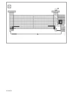
Страница 23: ...ca 700mm 1 2 3 4 5 01 05 2004 ...

Страница 24: ...maximal 1100mm 6 1100mm max 7 01 05 2004 ...

Страница 25: ...3 4 8 01 05 2004 ...

Страница 26: ...B P2 P3 12 24Vac LD1 LD2 12V 10W JP2 F1 10A F2 5A RADIO green red batt solar input 1 2 3 4 5 6 7 8 9 10 11 M2 M1 12 13 14 15 16 17 12V DC NO NO 1 2 1 2 3 2 3 9 10 11 12 01 05 2004 ...

Страница 27: ...13 2 1 2 1 Module 433MHz 418MHz 27MHz Logic Board 01 05 2004 ...

Страница 28: ...12V 12V NC min 0 5 mm 2 NC C NO 10 11 1 2 10 11 1 2 5m max 14 15 01 05 2004 40 cm ...

Страница 29: ...6 041DR3896 2 P2 P3 12 24Vac LD1 LD2 JP2 F1 10A F2 5A RADIO green red batt solar input 1 2 3 4 5 6 7 8 9 10 11 12 13 14 15 16 17 1 2 1 2 3 2 3 17 041DR296 2 041DR196 2 041DR996 2 041DR2296 041DR2696 041DR3996 041DR7096 041DR4096 041DR6896 041A801337 041A5408 CDS 433MHz 041DRWGO200 041ADCWGO200 01 05 2004 ...

Отзывы: