


Chapter 2
7
CN24 (Front Audio Connector)
This connector give you the option of a front panel audio jack
cable ext. to be plug into a special custom designed system case.
Simply remove the two jumper caps at pin [
5-6
] and [
9-10
] then
plug it into the (optional) cable ext. connector. Pin [
5-6
] and
[
9-10
] are shorted (default) to enable the back panel audio
function.
IR2 (IR Connector)
Select a UART Mode in BIOS's Integrated Peripherals menu the
UART port to support IR function. (See section
3.4
Super I/O
Device of
Integrated Peripherals
)
JP3 (Ext. Bus Frequency)
This function allows you to set the CPU frequency.
Pin
Definition
1-2 100
MHz
2-3 133
MHz
Chapter 3
8
Chapter 3
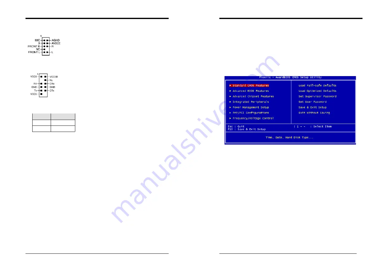
BIOS Setup Program
Phoenix-Award BIOS ROM has a built-in setup program that allows users to modify the
basic system configuration. This information is stored in CMOS RAM so that it can
retain the setup information, even when the power is turned off.
To enter the
Phoenix-Award BIOS
setup program press the [
Delete key
] when you
Power on
or
reboot
the computer system. The primary screen as shown in Figure 3-1 is a
list of the menus and functions available in the setup program. Select the desired item by
your arrow keys and press enter to make the changes. Operating commands are located at
the bottom of this and all other BIOS screens. When a field is highlighted, on-line help
information is displayed on the right side of the screen.
Figure 3-1 Setup Program Initial Screen
3-1 Standard CMOS Setup
The Standard CMOS Setup allows users to configure system components such as hard
disk drive, floppy disk drive and video display as well as date, time and boot-up error
signaling. This configuration menu should be changed when installing a motherboard for
the first time, changing hardware in your system such as the HDD, FDD, video display,
or when the CMOS data has been lost or contaminated. Choose the Standard CMOS
Setup option from the CMOS Setup Utility menu (Figure 3-1) to display the following
screen.
Date/Time
Set the date and time of the system. Do not skip this function as all of your timed events
such as power management, saving files, etc are based on this timer.
IDE (Primary/Secondary; Master/Slave)
This category identifies up to four IDE hard disk drives that have been installed in the
computer. This section does not show information on other IDE devices such as
CD-ROM drives or other hard drive type such as SCSI drives.
Drive A
Select different Floppy device Model. Available options are [None], [360K, 5-1/4 in],
[1.2M, 5-1/4 in], [720k, 3-1/2 in], [1.44M, 3-1/2 in], and [2.88M, 3-1/2 in].
Video
Select the type of video adapter present in your system. You can ignore this setting if you


