


Chapter 2
3
Chapter 2
Hardware Setup
If your motherboard has already been installed in your computer you may still need to
refer to this chapter if you plan to upgrade your system's hardware.
This motherboard is electrostatic sensitive. Do not touch without
wearing proper safety gadget and make sure to disconnect the power
cable from the power source before performing any work on your
motherboard. Not doing so may result in electrical shock!
2-1 Installing a CPU Processor for Socket A
The Socket A, designed for AMD® Athlon XP/Athlon/Duron processors, has been
incorporated as a standard motherboard specification. To insert your CPU into Socket A
please do the following:
1. Locate a cut edge on the top surface of the CPU close to one if it’s corners. The same
corner will also be cut off, leaving a noticeable notch in the CPU’s corner. These
markings indicate Pin 1 of the CPU.
2. Pull up the lever of Socket 462 so that it is perpendicular with the surface of the
motherboard. Gently insert the CPU with Pin 1 at the same corner of Socket 462 that
contains the end of the lever. Allow the weight of the CPU to push itself into place. Do
not apply extra pressure as doing so may result in damaging your CPU. Snap the lever
back into place.
Installing an AMD® approved heat sink with cooling fan is necessary for
proper heat dissipation from your CPU. Failing to install these items may
result in overheating and possible burnout of your CPU.
2-2 Setting Your CPU’s Performance
Frequency Configuration:
This motherboard uses a new user-friendly technology that enables the user to setup a
main board’s CPU parameters through an easy to use BIOS setup procedure. It is no
longer necessary to make many jumper settings as on conventional motherboard.
After installing all your hardware into your PC system, you can manually configure your
CPU clock according to your processor’s specifications. By turning on your system’s
power. Enable the CMOS Setup Utility by pressing the delete key when your BIOS
identification screen appears, then go to the Frequency/ Voltage control option and select
your CPU clock speed (please refer to Chapter3 for more details).
You do not need to make voltage settings because this board will automatically
set your CPU voltage.
2-3 Main Memory Configuration
The DDR SDRAM memory system consists two banks and can support the memory size
up to 1 GB per DIMM. If you only use one bank it does not matter which one you use
and if you use two or more banks, it does not matter which bank you install first.
DRAM Specifications
DIMM type: 2.5V, unbuffered 184 pin 64/128/265/512-bit DDR SDRAM.
Module size: Single/double-sided 64/128/256/512Mbytes or 1GBbtes.
Parity: Ether parity or non-parity.
Chapter 2
4
2-4 Connector and Jumper Settings
Connectors are used to link the system board with other parts of the system, including the
power supply, the keyboard, and the various controllers on the front panel of the system
case.
The power supply connector is the last connection to be made while
installing a motherboard. Before connecting the power supply, please
make sure it is not connected to the power source.
PW1 (ATX Power Supply Connector)
The power cord leading from the system's power supply to the external power source
must be the very last part connected when assembling a system. The ATX power supply
provides a single 20-pin connector interface, which incorporates st/-5V, +/-12V,
optional 3.3V and Soft-power signals. The Soft power signal, a 5V trickle supply is
continuously supplied when AC power is available. When the system is in the Soft-Off
mode, this trickle supply maintains the system in its minimum power state.
The ATX 12V power supply has a new +12V (4-pin) and +5V/3.3V (6-pin) auxiliary
power connector. To enable the delivery of more +12 VDC and +5/3.3V VDC current to
the motherboard.
Power-On By Modem
While in Soft-Off state, if an external modem ring-up signal occurs, the system wakes up
and can be remotely accessed. You may enable this function in BIOS's Power
Management Setup menu. (See section
3. 5
)
Blinking LED in Suspend Mode
While in Suspend mode, the LED light on the front panel of your computer will flash.
Suspend mode is entered by pressing the Override Power Button, pushing the Green
button on your ATX case, or enabling the Power Management and Suspend Mode options
in BIOS's Power Management menu. (See section
3.5
)
Poly-fuse Over Current Protection
The poly-fuse protects the system from dangerous voltages that the system might be
exposed to via the keyboard or USB connector. In case of such exposure, the poly-fuse
will immediately be disconnected from the circuit, just like a normal fuse. After being
disconnected for a certain period of time, the poly-fuse will return to its normal state.
Then the keyboard or USB connector can function properly again. Unlike conventional
fuses, the poly-fuse does not have to be replaced, relieving the user wasted time and
inconvenience.
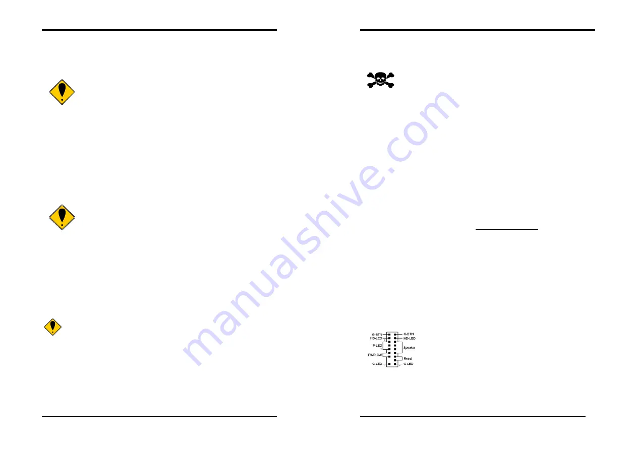
CN1A (Front Panel Connector)
1.
PWR-SW
(Over-ride Power Button Connector)
The power button on the ATX chassis can be used as a normal power
switch as well as a device to activate Advanced Power Management
Suspend mode. This mode is used for saving electricity when the
computer is not in use for long periods of time. The Soft-OFF by
PWR-BTTN function in BIOS's Power Management Setup menu must
be set to [
Delay 4 Sec.
] to activate this function.
When the Soft-OFF by PWR-BTTN function is enabled, pushing the
power button rapidly will switch the system to Suspend mode. Any occurrence of
external activities such as pressing a key on the keyboard or moving the mouse will
bring the system back to Full-On. Pushing the button while in Full-On mode for more
than [
4 seconds
] will switch the system completely off. See Over-ride Power Button
Operation diagram.


