


CET Electric Technology
55
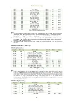
0082
RO
AI
1
Scaled
Float
-
0084
RO
Iresidual
1
Float
-
0086~0095
RO
Reserved
Float
-
0096
RO
DI Status
1,2
UINT16
-
0097
RO
Reserved
UINT16
-
0098
RO
DO Status
1,3
UINT16
-
0099
RO
Reserved
UINT16
-
0100
RO
Setpoint Status
4
UINT16
-
0101
RO
Wiring Diagnostic Status
5
UINT16
-
0102
RO
SOE Log Pointer
6
UINT32
-
0104
RO
Device Operating Time
7
UINT32
x0.1
0.1Hour
0106~0111
RO
Reserved
UINT32
-
0112
RO
Phase A Fundamental kW
Float
x1
W
0114
RO
Phase B Fundamental kW
Float
0116
RO
Phase C Fundamental kW
Float
0118
RO
Total Fundamental kW
Float
0120
RO
Total Harmonic kW
Float
0122
RO
DR #1 Log Pointer
6
UINT32
-
-
0124
RO
DR #2 Log Pointer
6
UINT32
-
-
0126
RO
DR #3 Log Pointer
6
UINT32
-
-
0128
RO
DR #4 Log Pointer
6
UINT32
-
-
0130
RO
DR #5 Log Pointer
6
UINT32
-
-
0132
RO
Daily Freeze Log Pointer
8
UINT16
-
-
0133
RO
Monthly Freeze Log Pointer
8
UINT16
-
-
0134~0148
RO
Reserved
UINT32
-
0150
RO
Uan/Uab (3P3W, 1P2W LL) Fundamental
Float
x1
V
0152
RO
Ubn/Ubc (3P3W) Fundamental
9
Float
0154
RO
Ucn/Uca (3P3W) Fundamental
9
Float
0156
RO
Ia Fundamental
Float
x1
A
0158
RO
Ib Fundamental
9
Float
0160
RO
Ic Fundamental
9
Float
0162
RO
U1 (Positive Sequence Voltage)
10
Float
x1
V
0164
RO
U2 (Negative Sequence Voltage)
10
Float
0166
RO
U0 (Zero Sequence Voltage)
10
Float
0168
RO
I1 (Positive Sequence Current)
10
Float
x1
A
0170
RO
I2 (Negative Sequence Current)
10
Float
0172
RO
I0 (Zero Sequence Current)
10
Float
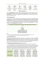
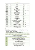
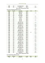
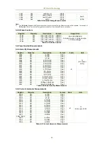
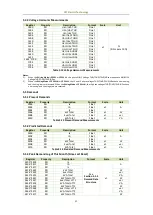
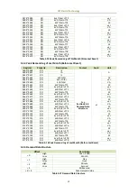
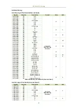
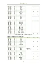
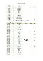
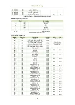
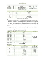
Table 5-1 Basic Measurements
Notes:
1)
I4, AI, Ir, DI Status and DO Status are only meaningful if the meter is equipped with the corresponding option.
2)
For the DI Status register, the bit values of B0 to B3 represent the states of DI1 to DI4, respectively, with “1” meaning
Active (Closed) and “0” meaning Inactive (Open).
3)
For the DO Status register, the bit values of B0 to B1 represent the states of DO1 and DO2, respectively, with “1”
meaning Active (Closed) and “0” meaning Inactive (Open).
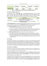
4)
For the Setpoint Status register, the bit values indicate the various Setpoint states with “1” meaning Active and “0”
meaning Inactive. The following table illustrates the details of the Alarm Status register.
Bit15
Bit14
Bit13
Bit12
Bit11
Bit10
Bit9
Bit8
Reserved
Reserved Reserved
Reserved
Reserved
Reserved
Reserved
Setpoint9
Bit7
Bit6
Bit5
Bit4
Bit3
Bit2
Bit1
Bit0
Setpoint8
Setpoint7
Setpoint6
Setpoint5
Setpoint4
Setpoint3
Setpoint2
Setpoint1
Table 5-2 Setpoint Alarm Status Register
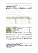
5)
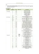
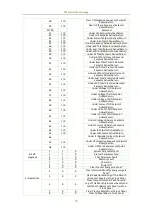
The following table illustrates the Wiring Diagnostic Status with 0 meaning Normal and 1 meaning Abnormal:
Bit
Event
B00
Summary Bit (Set if any other bit is set)
B01
Frequency is out of range (45 to 65Hz) (3P4W or 3P3W)
B02
Voltage Phase Loss (Register 6000) (3P4W only)
B03
Current Phase Loss (Register 6004) (3P4W or 3P3W)
B04
Reserved
B05
Reserved
B06
Voltage Phase Reversal (3P4W only)
B07
Current Phase Reversal (3P4W or 3P3W)
B08
Negative kW Total may be abnormal (3P4W or 3P3W)
B09
Negative kWa is may be abnormal (3P4W only)
B10
Negative kWb may be abnormal (3P4W only)
B11
Negative kWc may be abnormal (3P4W only)
B12
CTa polarity may be reversed (3P4W only)


