


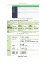


CET Electric Technology
44
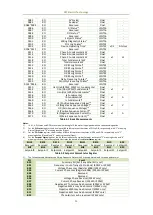
Under Limit
Specify the value that the setpoint parameter must go
below for Over Setpoint to become inactive or for Under
Setpoint to become active.
0*
Active Delay
Specify the minimum duration that the setpoint condition
must be met before the setpoint becomes active. An event
will be generated and stored in the SOE Log. The range of
the Active Delay is between 0 and 9999 seconds.
0 to 9999s
Default=10
Inactive Delay
Specify the minimum duration that the setpoint return
condition must be met before the setpoint becomes
inactive. An event will be generated and stored in the SOE
Log. The range of the Inactive Delay is between 0 and 9999
seconds.
0 to 9999
Default=10
Setpoint Trigger
Specify what action a setpoint would take when it becomes
active. Please refer to Table 4-8 below for a list of Setpoint
Triggers.
See Table 4-8
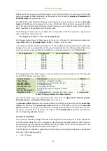
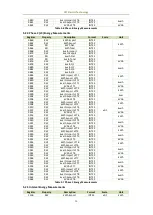
Table 4-6 Description for Setpoint Parameters
The table below illustrates the Setpoint Parameters. In addition, the LCD would blink when a setpoint
becomes active and if the SP LCD Alarm (Register #6048) is set to Enable.
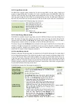
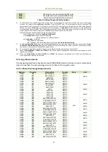
Key
Setpoint Parameter
Scale
Resolution
Unit
0
None
-
-
-
1
Uln (Any Phase Voltage)
x1
0.001
V
2
Ull (Any Line Voltage)
3
I (Any Phase Current)
A
4
In (Calculated)
5
Frequency
0.01
Hz
6
P (kW Total)
0.001
W
7
Q (kvar Total)
var
8
S (kVA Total)
VA
9
PF (PF Total)
-
10
P DMD (kW Total Present Demand)
W
11
Q DMD (kvar Total Present Demand)
var
12
S (kVA Total Present Demand)
VA
13
P DMD Pred (kW Total Predicted Demand)
W
14
Q DMD Pred (kvar Total Predicted Demand)
var
15
S DMD Pred (kVA Total Predicted Demand)
VA
16
U THD
0.01%
100%
17
U TOHD
100%
18
U TEHD
100%
19
I THD
100%
20
I TOHD
100%
21
I TEHD
100%
22
U Unbal (Voltage Unbalance)
100%
23
I Unbal (Current Unbalance)
100%
24
Reversal (Phase Reversal)
1, 2
-
-
-
25
I4 (Measured)*
x1
0.001
A
26
AI*
1
-
27
IR (Residual Current) *
x1
0.001
A
28
U2 (Voltage Negative Sequence
Component)
x1
V
29
U0 (Voltage Zero Symmetrical Component)
* Appear only if the device is equipped with the appropriate option.
Table 4-7 Setpoint Parameters
Notes:
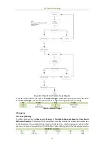
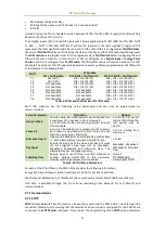
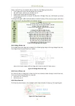
3.
When Reversal is set as the Setpoint Parameter, the Setpoint Type should be set to 1 (i.e., Over Setpoint). The Setpoint
Type=2 (i.e., Under Setpoint) is invalid.
4.
When Reversal is set as the Setpoint Parameter (with Setpoint Type=1), the Over Limit should be set as 0 and Under Limit
should be as 1. The logic diagram for the Phase Reversal setpoint is illustrated in the following figure:


