


CET Electric Technology
27
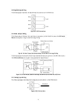
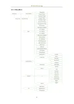
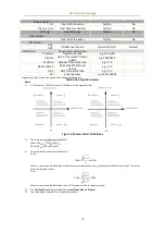
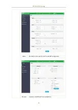
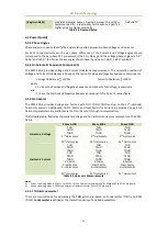
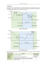
Figure 3-6 Reversal Setpoint Logic Diagram
6)
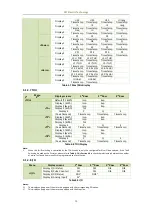
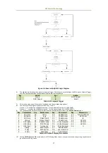
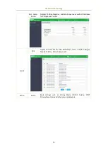
The table below illustrates the options for Setpoint Trigger. Please keep in mind that when the DOx is set as Setpoint Trigger,
the DOx Function should be configured as Digital Output correspondingly.
Key
Action
Key
Action
0
None
1
DO1 Closed
2
DO2 Closed
3
Table 3-12 Setpoint Trigger
7)
This menu only appears if the meter is equipped with the corresponding options.
8)
The Delimiter setup register supports two options, 1 and 2:
Option 1: “,” is used as the x1000 delimiter and “.” as the decimal point (e.g. 123,456,789.0).
Option 2: “ ” is used as the x1000 delimiter and “,” as the decimal point (e.g. 123 456 789,0).
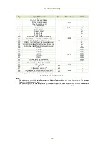
9)
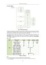
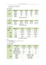
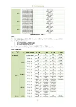
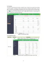
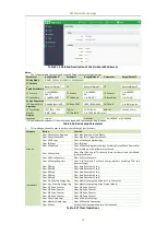
The following table illustrates the parameters that can be selected for display in the Default Display screen.
Key
Parameters
Key
Parameters
Key
Parameters
Key
Parameters
0
U1 (Uan)
10
I3 (Ic)
20
T1 kWh Imp
30
Fund. kW Total
1
U2 (Ubn)
11
Iavg
21
T2 kWh Imp
31
dPF Total
2
U3 (Ucn)
12
P (kW Total)
22
T3 kWh Imp
32
I4
3
Ulnavg
13
Q (kvar Total)
23
T4 kWh Imp
33
U1 THD
4
U12 (Uab)
14
S (kVA Total)
24
I1 (Ia) Demand
34
U2 THD
5
U23 (Ubc)
15
PF (PF Total)
25
I2 (Ib) Demand
35
U3 THD
6
U31 (Uca)
16
Frequency
26
I3 (Ic) Demand
36
Ir
7
Ullavg
17
kWh Import
27
kW Demand
8
I1 (Ia)
18
kWh Export
28
kvar Demand
9
I2 (Ib)
19
kWh Total
29
kVA Demand
Table 3-13 Default Display Parameters
10)
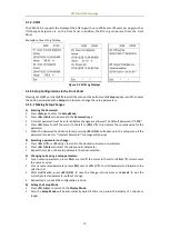
Setting SP LCD Alarm to On would make the LCD blinking when there is a Setpoint occurred and pressing any buttons to
go to the first SOE log screen.


