CET Electric Technology
77
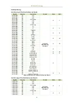
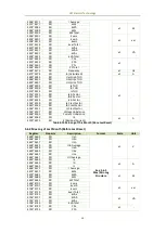
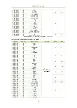
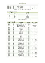
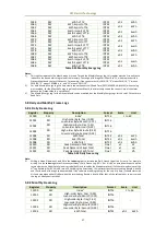
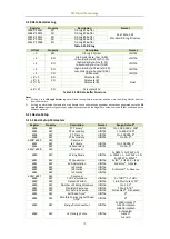
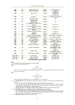
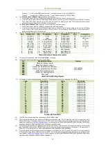
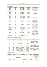
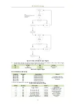
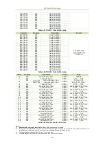
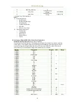
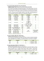
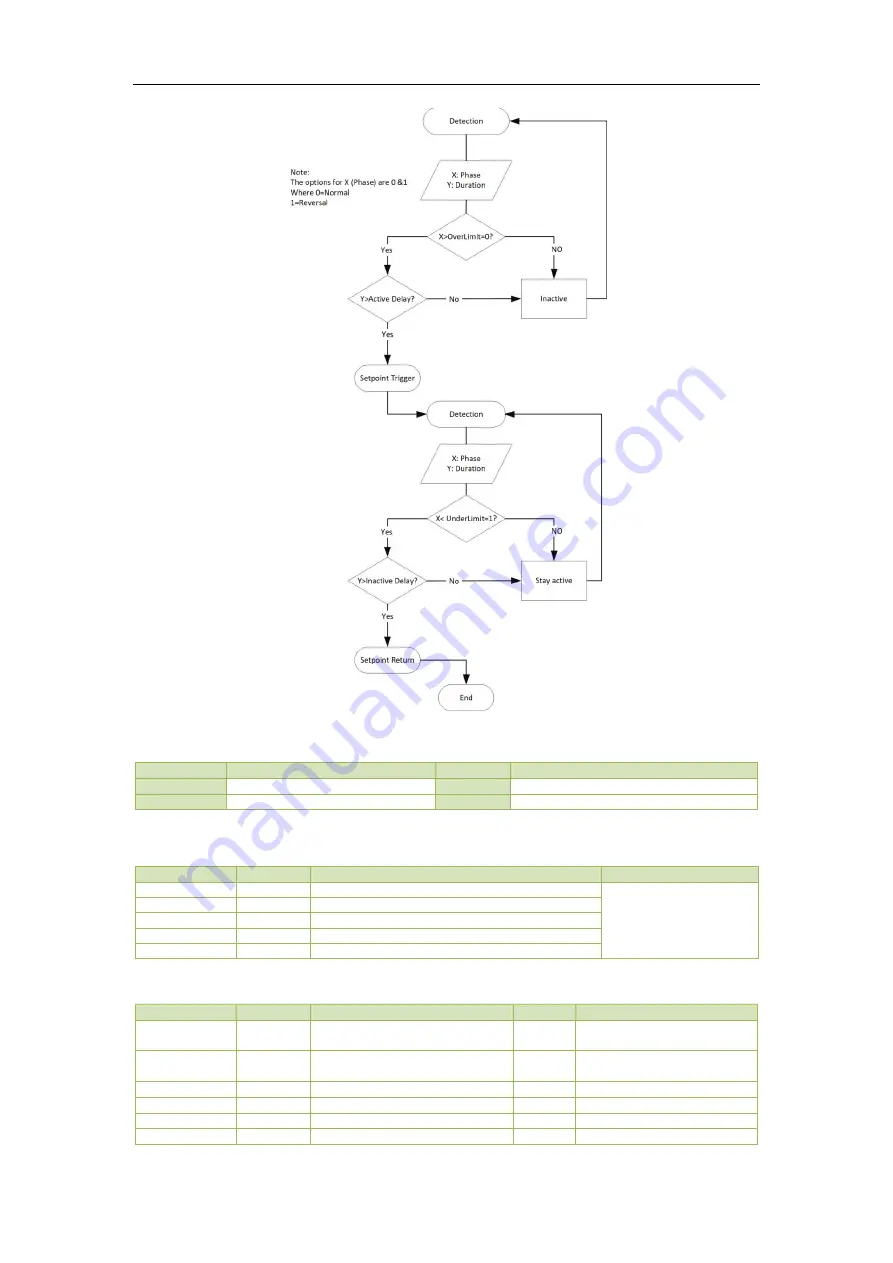
Figure 5-1 Reversal Setpoint Logic Diagram
3)
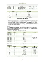
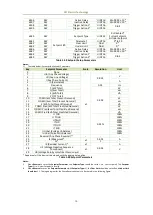
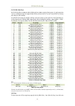
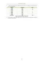
The table below illustrates the options for Setpoint Trigger. Please keep in mind that when the DOx is set as Setpoint Trigger,
the DOx Function should be configured as Digital Output correspondingly.
Key
Action
Key
Action
0
None
1
DO1 Closed
2
DO2 Closed
3
Table 5-41 Setpoint Trigger
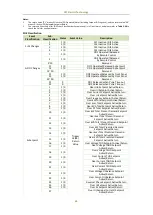
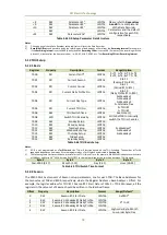
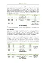
5.11.5 Data Recorder Setup
Register
Property
Description
Format
6600~6623
RW
Data Recorder #1*
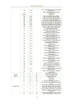
See Table 5-43 DR
Setup Parameter Data
Structure
6624~6647
RW
Data Recorder #2*
6648~6671
RW
Data Recorder #3*
6672~6695
RW
Data Recorder #4*
6696~6719
RW
Data Recorder #5*
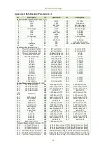
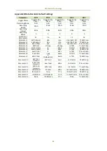
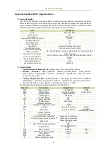
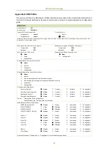
* Please refer to Appendix B for the default configuration for the Data Recorders.
Table 5-42 Data Recorder Setup
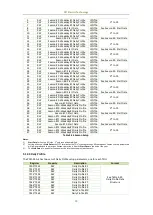
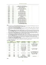
Offset
Property
Description
Format
Range
+0
RW
Trigger Mode
UINT16
0=Disabled
1=Triggered by Timer
+1
RW
Recording Mode
1
UINT16
0=Stop-when-Full
1=First-In-First-Out
+2
RW
Recording Depth
1
UINT32
0 to 120,000
+4
RW
Recording Interval
1
UINT32
60 to 3,456,000 s
+6
RW
Recording Offset
2
UINT16
0 to 43,200 s
+7
RW
Number of Parameters
1
UINT16
0 to 16

