14
MB Pool & spa heater
VENTILATION REQUIREMENTS
The heater must have both ventilation and combus-
tion air. Safe and effi cient operation of the heater is
vitally dependant upon a good supply of fresh air to
the room in which the appliance is installed. Minimum
requirements for net free air supply openings direct
to outside air at both high and low level are detailed
in the table at the bottom of this page.
Position grilles to avoid the risk of accidental block-
age or fl ooding. Further guidance is given in BS6644.
CAUTION:
Combustion air must not be contaminat-
ed by corrosive chemical fumes which can damage
the heater and void the warranty.
NOTE:
The design is also certifi ed by Advatica
for indoor installation when fi tted with appropriate
manufacturer's draught diverter and a suitable fl ue
system to outside. The heater must be in a room
separated from living rooms and provided with
appropriate ventilation direct to outside. It must not
be installed in a cupboard or compartment which is
directly connected to a living space.
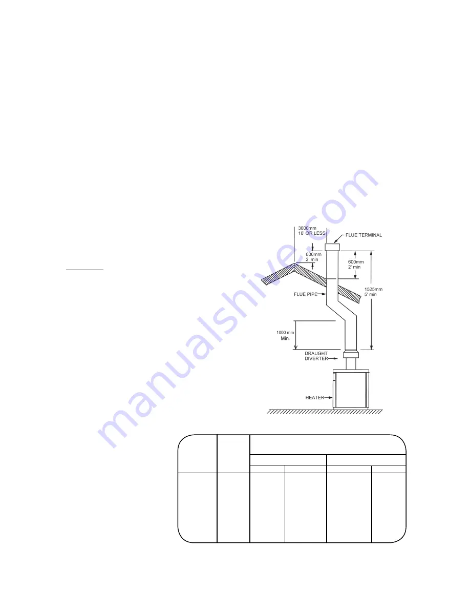
FLUE SYSTEM
WARNING:
Indoor boilers require a draught diverter that must
be connected to a fl ue pipe and properly fl ued to the
outside. Failure to follow this procedure can cause
fi re or fatal carbon monoxide poisoning.
To ensure safe and satisfactory operation of the heat-
er, the fl ue system must be capable of the complete
evacuation of fl ue products at all times. The effective
height of the fl ue terminal above the draught diverter
must ensure suffi cient buoyancy to overcome the re-
sistance of the bends and horizontal runs of the fl ue
pipe. The number of bends and length of horizontal
run must be kept to a minimum to reduce resistance.
The chimney must terminate in a downdraught free
zone.
The fl ue/chimney design should avoid the formation
of excessive quantities of condensate and for this
reason it is recommended that all chimneys are suit-
ably insulated and lined.
The draught diverter supplied with the heater must
be used.
Drain points should be fi tted at the bottom of all ver-
tical fl ue sections. Drain pipes must be a minimum
of 25mm (1 in) internal diameter and manufactured
from acid condensate resistant material (eg stainless
steel) and positioned so that pipe runs and discharge
points are not subject to the effects of frost and that
fl ue gases cannot leak into the room.
Any terminal fi tted must be of a type acceptable to
British Gas plc.
As part of commissioning, the fl ue must be satisfac-
tory when tested for fl ue fl ow and spillage as detailed
in BS5440 Part 1.
Flue.pcx
Model
Input Plant Room (cm
²
)
ref. BS5440 for models under 70kW
(kW)
Inside
Outside
High Low
High
Low
055
13
117 234
59
117
105
27 243 486
122
243
155
39
351 702
176
351
185
50
450 900
225
450
265
72
-
-
297
600
405
108
-
-
378
756
ref. BS6644 for models over 70kW
Compliance with the recom-
mendations made in BS 6644;
British Gas publication IM11
"Flues for Commercial and
Industrial Gas fi red boilers and
air heaters" and the "Third Edi-
tion of the 1956 Clean Air Act
memorandum" should be strictly
observed where applicable.


