19
MB Pool & spa heater
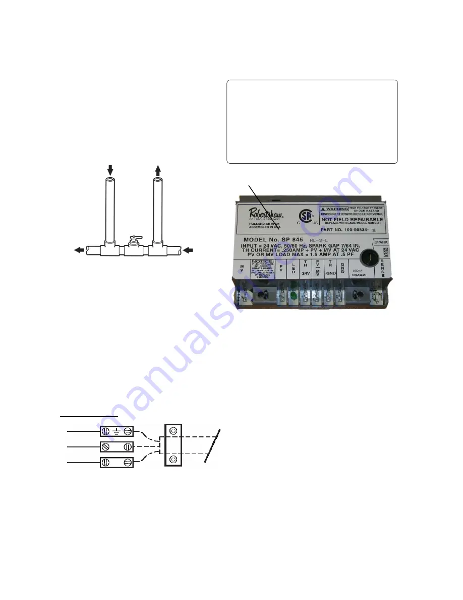
EXTERNAL AUXILIARY BYPASS VALVE
(Where Required)
An auxiliary bypass valve should be used when fl ow
rates exceed those shown in the table in the 'Con-
nections' section on p18. (usually a high performance
pump size larger than two HP will exceed this fl ow
rate). This valve is required to complement the func-
tion of the automatic bypass valve, particularly when
starting the heater in winter or early spring when the
spa or pool temperature is down below 10°C. It also
serves to eliminate needless pressure drop through
the heater and accompanying reduction in the fl ow
rate to the spa jets, etc.
From Heater
To Heater
To Pool
From
Pool
AUXILLARY BYPASS VALVE
(DO NOT USE GATE VALVE)
AUXILIARY BYPASS VALVE ADJUSTMENT
To set bypass: With clean fi lter, adjustment is made
by feeling the inlet and outlet pipes at the heater.
Outlet pipes should be slightly warmer than inlet and
comfortable to the touch. If pipe is hot, close bypass;
if cold, open bypass.
Wiring external to the appliance must be in accor-
dance with the IEE Wiring Regulations and any local
regulations which apply.
A 3 pin unswitched shuttered socket outlet, fused at
3A must be provided near to the heater, this should
serve only the heater together with its controls and
pumps.
Wiring should be 3 core PVC insulated (minimum,)
not less than 24 x 0.2mm. All fuses must be ASTA
approved to BS1362.
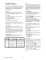
Connect the power supply as shown above. Ensure
that the cable is clamped in the cable clamp. The
wires must be such that the current carrying con-
ductors become taut before the earth conductor in
the event of the cable clamp not gripping the cable
adequately.
NOTE:
Input power to the heater (220V) should be
supplied from the load (Pump) side of time clock
or switch. Connecting heater to continuous power
source will allow "Fail" indications (service and pres-
sure switch) when pump is not operating.
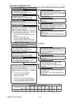
The Electronic Ignition Device automatically lights
the pilot and main burners upon a call for the heat.
The heater is supplied with a transformer for 230V
mains input.
NOTE:
Heater is equipped with an electronic ignition device
with a 100% safety lockout feature. If the heater
fails to start or lockout, reset the ignition device by
interrupting the power to the heater for 10 seconds.
Caution: If service replacement of the electronic igni-
tion device is required, replace only with the ignition
component supplied as a required spare.
Ignition Device.
ELECTRICAL WIRING
NOTE
:
If it is necessary to replace any of the origi-
nal wiring, it must be replaced with 105° C wire or
its equivalent, except all black wire which must be
replaced with 150° C wire or its equivalent.
NOTE: Heaters are factory wired for 230V power
supply.
NOTE: 22mm Dia. holes not utilized on jacket and
control box can be used for fi reman switch or auxiliary
control interface wiring.
GREEN/YELLOW
BLUE
BROWN
INTERNAL WIRING
N
L


