Cembre LD-2ENY Скачать руководство пользователя страница 9

8

27

All the broach cutters allow automatic cooling by means of the SR5000 unit supplied with 

the drills.

3.7) BROACH CUTTERS
These cutters rapidly produce high quality, accurate 
holes in a single pass. The automatic lubrocooling 
system reduces friction and eliminates heat build up 
during the drilling operation. Under standard conditions 
a broach cutter can drill 40-50 holes, depending on 
the hardness of the rail.

15128
15130
15132
15234
TSC 1 1/8"
15138
TSC 1 1/4"
TSC 1 5/16"
15144
15146
TSC 1 1/2"
TSC 3/4"
01354
01355
01356
01357
01358
01359
01360
01361
01362
01363
01364
12218
3-12224
3-12226
3-12228
3-12230
3-12232
3-12236

BROACH 

CUTTER

PILOT 

BIT

HOLE

DIAME-

TER

(inches)

7/8"

15/16"

1"

1 1/16"

1 1/8" 

1 3/16"

1 1/4" 

1 5/16"

1 3/8"

1 7/16"

1 1/2" 

3/4"
7/8"

15/16“ 

1“ 

1 1/16"

1 1/8" 

1 3/16“

1 1/4"

1 5/16“

1 3/8" 

1 7/16"

1 1/2" 

9/16" 

3/4" 

13/16"

7/8" 

15/16"

1"

1 1/8"

MAX. 

DEPTH OF CUT

(inches)

Ref. PPC 2

Ref. PPL 2

3-10528

2 "

7/8 "

3 "

APPENDIX “A”

Factors which infl uence the number of holes that can be made according to the 
tool used.

–  Hardness of the material to be drilled.
–  Thickness to be drilled.
–  Stability of the drill clamp
 and correct assembly of the cutter/bit.
–  Suitable lubrocooling (lubrication/cooling) to keep the temperature of the tool low so 
as not to compromise the effi ciency of the cutting edges, whilst at the same time facilitating 
the removal of the swarf.
–  Contact time of the cutting edges of the cutter/bit with the material to be drilled; 
bear in mind that the faster the hole is made the greater the effi ciency.
– Observance:
1)  Commence drilling by exerting light pressure on the advancing lever, progres-
sively increasing and then relaxing it when the tool is in the exit phase.
2)   Avoid pressure jolts and only advance according to the drilling diameter to avoid scratch-
ing the material or damaging the cutting edges of the cutter/bit.
3)  Remember that a tool with effi cient cutting edges requires a pressure lower than that 
applied to one with which a certain number of holes have already been made.
4)  When holes are made close to raised lettering on the rails, commence drilling 
with very light pressure
 until the lettering disappears, to avoid possible breakage of the 
tool.
5)  Bear in mind that when operating on very hard rails, as in the case of quality 1100 steel, 
it is advisable to increase the lubrocoolant fl ow rate.

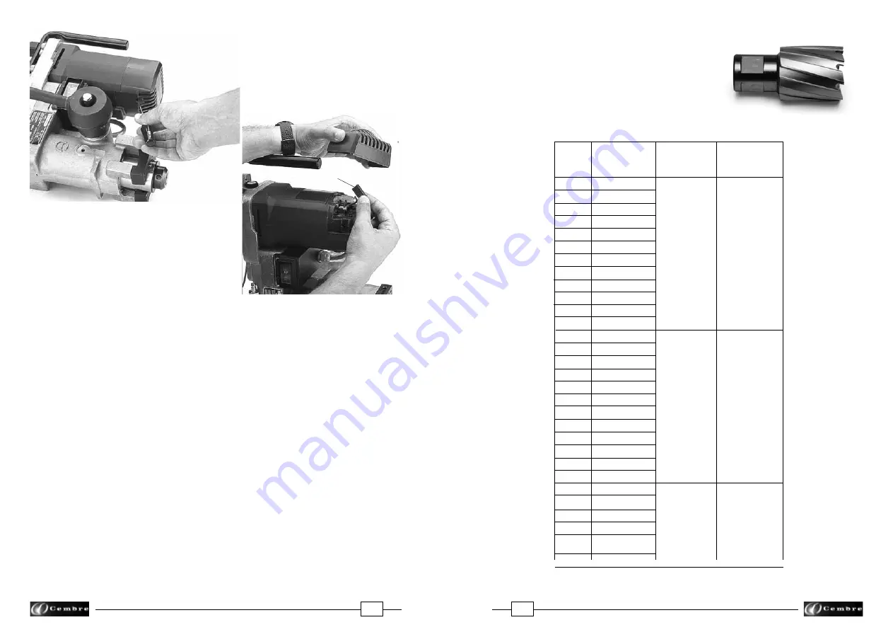
FIG. 26 – CHANGING THE BRUSHES 

Brush

Содержание LD-2ENY

Страница 1: ...nce T l 01 60 49 11 90 Fax 01 60 49 29 10 B P 37 91421 Morangis C dex E mail info cembre fr www cembre fr Cembre Espa a S L Calle Verano 6 y 8 P I Las Monjas 28850 Torrej n de Ardoz Madrid Espa a Tel...

Страница 2: ...neral characteristics 2 2 Accessories supplied with the rail drill 3 3 Optional accessories to be ordered separately 4 4 Type SR5000 coolant unit 10 5 Spindle advancing lever 12 6 Preparing the rail d...

Страница 3: ...e page 28 RAIL DRILL TYPE LD 2ENY NOTES ATTENTION Before using the rail drilling carefully read the instructions contained in this manual SAVE THESE INSTRUCTIONS this manual contains important safety...

Страница 4: ...ving the drilling swarf 2 8 4 7 fl oz 140 ml oil tank for the gear reduction 2 9 Type SR5000 coolant unit Accessories from pos 2 1 to pos 2 8 are included in the Kit of accessories for LD 2ENYY having...

Страница 5: ...ings complete with the TDB 6 termination Always supplied with rail drill ref LD 2EY 3 1 2 DBG GR device for clamping the rail drill in correspondance of guard rail complete with theTDB 1 termination A...

Страница 6: ...4 H FIG 27 DBG Y RAIL WEB CLAMPING DEVICE 6001154 6700524 6040421 6001155 6001156 6760378 6340612 6900314 6650144 6900348 6760222 6140082 6001775 6001751 6001756 6001754 6340160 6380310 6001150 60016...

Страница 7: ...64 100 LB RE 2 45 64 100 LB RE HF 2 45 64 100 LB PRR 2 9 32 100 LB PS 2 31 64 105 LB DY 110 LB RE 2 43 64 112 115 119 LB RE 2 7 8 122 CB 2 7 8 127 LB DY 3 1 8 130 LB RE HF A 2 3 4 130 LB RE HF 3 1 16...

Страница 8: ...WA is equal to 96 6 dB A Protection of operators against risksof exposure to noise during work Cembre drills type LD 2EY are designed and constructed according to EEC directives 80 1107 and 86 188 rel...

Страница 9: ...y of the drill clamp and correct assembly of the cutter bit Suitable lubrocooling lubrication cooling to keep the temperature of the tool low so as not to compromise the efficiency of the cutting edge...

Страница 10: ...3 8 Y included in the APED 130 included in the APED 135 165 DPE DPE included in the APED 130 DPE DPE DPE DPE DPE not required not required not required not required not required not required TST50 DB...

Страница 11: ...screw it back in the appropriate housing FIG 24 REMOVAL OF METALLIC RESIDUE 21 13 MAINTENANCE The type SR5000 coolant unit consists of a tank complete with tube and maximum pressure valve 01 fitted w...

Страница 12: ...manual external cooling when cutters are used to enlarge existing holes or when using spiral bits not de signed for automatic cooling If necessary the ARE adaptor can also be used to clean various par...

Страница 13: ...th the release pawl 39 pressed the lever is releasedfromitshubandcanrepeattheprevious travel without the spindle moving 11 STORING THE RAIL DRILL When work has been completed store the drill by procee...

Страница 14: ...rovided to insert the spiral bit if necessary rotate the spindle shaft manually and sufficiently by inserting the 4 mm male hexagon key in the appropriate intermediate gear housing in the crankcase of...

Страница 15: ...l then switched off after drilling by closing the tap FIG 20a COOLING DRILLING WITH SPIRAL BIT use only for APE do not required for APED 6 2 2 Insert into the spindle shaft the DPE spacer required to...

Страница 16: ...dfinallyrelievingthepressurein the exit phase When drilling close to raised markings on the rail the initial pressure must be extremely light until the markings disappear otherwise the cutter may be d...

Страница 17: ...drill fitted with short type broach cutter depth of cut 7 8 The drilling sequence may be started with the drill fitted with the broach cutter 6 1 positioning shoe 7 3 the drill being clamped to the r...

Страница 18: ...n the element to be drilled To position the drilling machine complete with the clamping termination 7 1 and the positioning template 7 3 suitable for the type of rail to be drilled proceed as follows...

Отзывы: