73
128. Select
“OK.”
129. Select
“
Sensors
.”
Note:
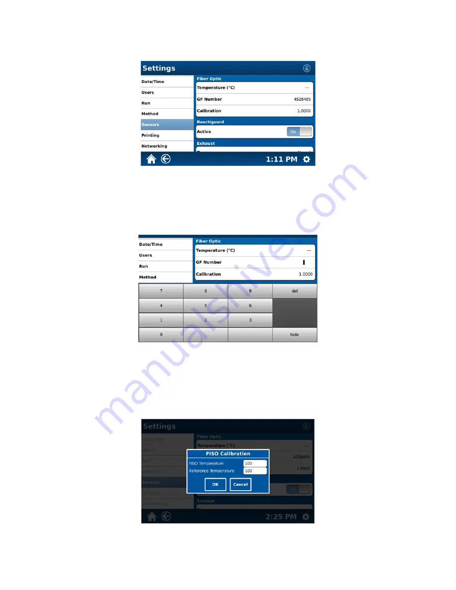
The sensor screen permits identification, on/off settings and calibration for the system sensors (Fiber Optic,
Reactiguard, Exhaust, IR and Pressure).
130. If a fiber optic probe is installed in the instrument, the above screen will display the GF number of the sensor.
131. If a GF number (found on the fiber optic probe) needs to be entered, select “GF Number.”
132. Using the keyboard, enter the GF Number of the fiber optic probe installed in the instrument. Once the number
is properly entered, select “hide” to close the keyboard.
133. To calibrate the fiber optic probe, select “Calibration.”
Note:
The fiber optic probe should be removed prior to removal of the control vessel from the instrument.
134. Place a beaker with approximately 250 mL of room -temperature water in the instrument cavity. Place the fiber
optic probe in the water to measure the temperature. Record the measured temperature on the probe.
Содержание MARS 6
Страница 1: ...Operation Manual Microwave Reaction System...
Страница 5: ...iv Ordering Information 92 Specifications 93 Warranty 95...
Страница 13: ...8...
Страница 39: ...34 4 Scroll the Method Information screen to view the remainder of the method information as illustrated below...
Страница 47: ...42 Power Time Graph Temperature Time Graph Temperature in Vessel Graph...


