background image

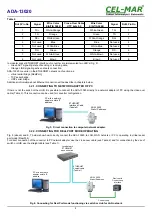
5.2.2.1.4. SERIAL BRIDGE PROFILE CONFIGURATION

Choosing the 

Serial Bridge

 profile, enable direct communication between two devices connected to two ADA-13020 converters over

the network as if they were connected with a serial cable. A properly configured ADA-13020 will start automatically communication
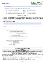
with each other. Press [

Apply

] for save the configuration

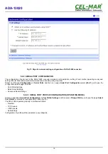
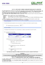
After saving the Serial Bridge profile, will open section 

Serial Bridge Settings

 with operating parameters like on picture below. Select

Initiate serial bridge to the following device  

option and enter IP address and 2101 Port of ADA-13020 with which to create the

serial bridge over the network. Additionally, can be selected [

Enable TCP Keep-Alive

] option which keeps connection even if the data

is  not  transmitted.  Select  

Allow  other devices  to initiate   serial  bridge  

and  enter  2101   port on  which  other  the  converter  will

automatically start communication and can be set also  [

Enable TCP Keep-Alive

] option which keeps connection even if the data is

not transmitted.

Fig 23. Example configuration of Serial Bridge TCP

ATTENTION !

Default port of serial port service is 2101.

If on the local network is conflict with other network service using the same port, in the converter's port configuration

change number of port into another for the server and client service.

5.2.2.1.4.1. CONFIGURATION OF SERIAL PORT TRANSMISSION PARAMETERS

For proper operation of ADA-13020 with device connected to his Current Loop serial port, should be set the same transmission

parameters for both devices. 
Select 

Basic Serial Settings 

and enter 

Baud Rate

Data Bits

Parity

Stop Bits,

 the same parameter like has device connected to

the serial port of the converter.

5.2.3. SYSTEM SETTINGS

Select on left panel menu 

Configuration -> System 

and then on right will be selections as follows:

Device Identity Settings

 – allows adding name of converter, describe the location and add identification number,

Simple Network Management Protocol Settings (SNMP) 

– allows to make the configuration of management protocol SNMP.

5.2.4. USERS AND PERMISSIONS

On the configuration page 

Users

 are two sections:

Users

Configure Users

The section 

Users 

allows configuring the method of login to ADA-13020. Selecting the option 

Enable user logins 

means that after

enter   the   address  

http://<


 c  on

   v  erter-


 ip-address


 >/admin/administration.htm

  to   internet   browser,   will   open   login   window  and   will   be

necessary to enter user name and password.
The section 

Configure Users 

allows adding additional user, change password, configure access and permissions for each defined

users.

5.2.4.1. CHANGING USER NAME AND PASSWORD

Changing the default user root and password, can be done as follows :
1. press user mane 

root

 in section 

Users Configuration->Configure Users,


2. enter new user name and password.
3. press [

Apply

] for saving.

5.2.4.2. ADDING   NEW   USER   WITH   LIMITED   PERMISSIONS   FOR   CONFIGURATION   OR
MANAGEMENT 

For adding new user with limited permissions for configuration or management follow the steps below:
1.From menu 

Configuration 

select 

Users,

2. In section 

Configure Users, 

press

 [New...]

,

3. Enter user mane (eg. 

admin

) and password – twice, and press 

[Apply]

,

4. Will open the page 

Users Configuration

, where in section 

Configure Users

, will be new user name.

Now it is possible to configure access permissions to the converter and permissions for configuration of this new user.

Configuration of access to converter:

21

ADA-13020

Содержание ADA-13020

Страница 1: ...User manual ADA 13020 ETHERNET to Current Loop Converter 1 io_ada 13020_v1 14_en ADA 13020 Copyright 2001 2017 CEL MAR sp j...

Страница 2: ...ORK SETTING 13 5 2 CONFIGURATION AND MANAGEMENT BY THE USE OF INTERNET BROWSER 15 5 2 1 NETWORK SETTING CONFIGURATION 15 5 2 2 SERIAL PORT CONFIGURATION 16 5 2 2 1 SERIAL PORT PROFILE CONFIGURATION OP...

Страница 3: ...6 2 REALPORT CONFIGURATION IN WINDOWS XP 23 7 FACTORY DEFAULT 25 8 TROUBLESHOOTING 25 9 VERSIONS 25 10 SPECIFICATION 26 3 ADA 13020...

Страница 4: ...network is only after disconnecting the power supply circuit voltage Do not carry out the assembly or dis assembly of the device if it is enabled This may result to short circuit and damage the devic...

Страница 5: ...ade on base safety diodes and fuses on each Current Loop lines To Current Loop interface can be connected one device in point to point topology operates in half duplex or full duplex mode This convert...

Страница 6: ...CURRENT LOOP TRANSMITTER The Current Loop transmitter at ADA 13020 is made as active on the base power source generate current depend on converter s version 20mA or 0 20mA TTY The transmitter has a sh...

Страница 7: ...ll the device on TS 35 should be the upper part of the casing put hooks on the terminal and then press the bottom of the cover until you hear a characteristic Click sound 3 2 ETHERNET NETWORK CONNECTI...

Страница 8: ...OF PC If there is not the switch or the HUB it is possible to connect the ADA 13020 directly to a network adapter of PC using the cross over cable Table 2 This connection can be used for converter co...

Страница 9: ...8 Connecting for functioning in TCP UDP serial bridge mode one to one in LAN network 9 ADA 13020 ROUTER Public IP address ETHERNET Straight cable Tabela 1 ETHERNET Straight cable Tabela 1 Current Loop...

Страница 10: ...device with active transmitter passive receiver 10 ADA 13020 Current Loop Current Loop Current Loop ADA 13020 Static IP address SLAVE Device with Device with Current Loop interface interface ADA 1302...

Страница 11: ...the Current Loop BUS like on the picture below In this case Current Loop bus is created by eg one converter ADA 13020 1 1 2 2 3 MASTER Active Transmitter one converter ADA 1020 1 1 2 2 3 SLAVE Active...

Страница 12: ...otection from opposite connection power supply 12 ADA 13020 SLAVE 2 RS232 SLAVE 15 RS232 ADA 1020 1 2 2 3 SLAVE PASSIVE 1 SLAVE 1 RS232 RS232 Rx Rx Rx Tx Tx DB 9F RS232 connector Rx Rx Rx Tx Tx DB 9F...

Страница 13: ...AWiz are available in Start Programs CEL MAR ADANet 5 1 2 NETWORK SETTING The ADAFinder is use for configuration of converter s network setting Before running the ADAFinder should be disabled the Syst...

Страница 14: ...Fig 14 Basic network configuration Fig 15 IP address setting 14 ADA 13020...

Страница 15: ...ow Fig 16 Page for manage and configuration of ADA 13020 converter 5 2 1 NETWORK SETTING CONFIGURATION To make changes of default setting or new configuration of ADA 13020 select on left panel Configu...

Страница 16: ...erial Port Configuration select Port 1 will open the configuration details page includes Port Profile Settings Basic Serial Settings Advanced Serial Settings 5 2 2 1 SERIAL PORT PROFILE CONFIGURATION...

Страница 17: ...5 2 2 1 2 TCP SOCKETS CONFIGURATION Choosing TCP Sockets is configured the serial port of ADA 13020 for direct communication with PC by the use of TCP socked Data sending by application to TCP socked...

Страница 18: ...e is 2101 If on the local network is conflict with other network service using the same port in the converter s port configuration change number of port into another for the server and client service...

Страница 19: ...ofile will open section UDP Server Settings with operating parameters like on picture below Set access to UDP server on e g 2101 port Then select Automatically send serial data in section UDP Client S...

Страница 20: ...working UDP Server of converter connected to MASTER device and press Add In the section Send data under any of the following conditions is recommended to set parameters like on picture bellow For sav...

Страница 21: ...ts Parity Stop Bits the same parameter like has device connected to the serial port of the converter 5 2 3 SYSTEM SETTINGS Select on left panel menu Configuration System and then on right will be sele...

Страница 22: ...tore the factory default settings to display system details information to reboot the converter 5 2 6 1 FILE MANAGEMENT Section File Management enables upload and delete Web provided by manufacturer U...

Страница 23: ...Open 6 when the installation window will appear press Next 7 will start the searching for converters in the network 8 if no devices were not found press Next 9 should be set in the window Describe the...

Страница 24: ...Fig 24 Device view on Windows XP Fig 25 Example configuration of multi port serial adapter 24 ADA 13020...

Страница 25: ...ec when the converter will start with default settings Restoring Default Settings deletes existing configuration and the proper configuration should be loaded to the converter from the backup I change...

Страница 26: ...nalization PWD green LED power supply RX red LED data reception on Current Loop port TX yellow LED data transmission via Current Loop port Electrical Parameters Power requirements 10 24 30 V DC Power...

Страница 27: ...27 ADA 13020...

Страница 28: ...a transmission converters with interface RS232 RS485 RS422 USB Current Loop Fibre Optic Converters and Ethernet or Wi Fi Please contact us to tell how you like our products and how we can satisfy you...

Отзывы: