


Installation and operation manual
ELS 300
© CEDES/October 2016
www.cedes.com
5
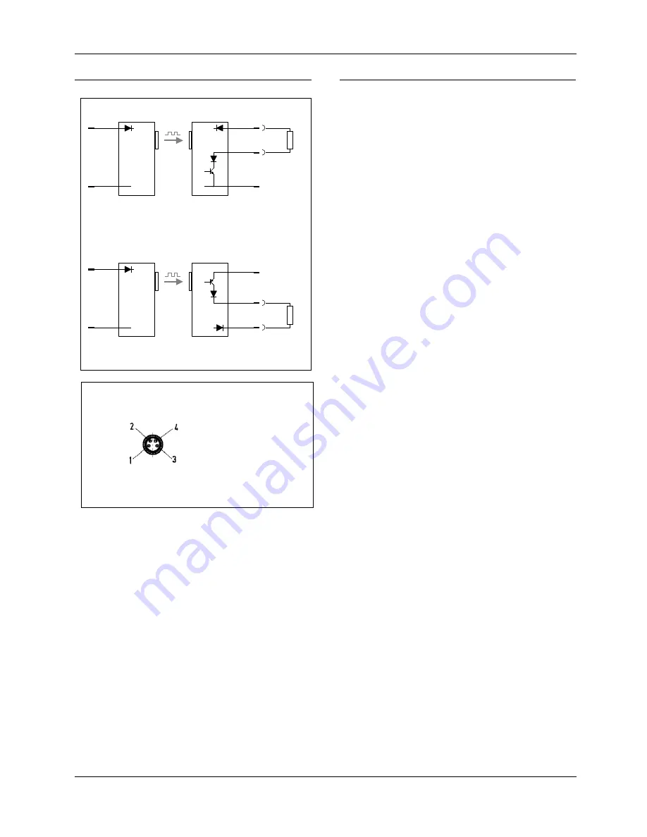
5.1. Connecting diagram
brown
(pin 1)
blue
(pin 3)
+10...30VDC
black
(pin 2)
brown
(pin 1)
blue
(pin 3)
GND
+10...30VDC
Out
GND
ELS 300 Tx-...
ELS 300 Rx-NPN/...
+10...30VDC
GND
+10...30VDC
Out
GND
ELS 300 Tx-...
ELS 300 Rx-PNP/...
brown
(pin 1)
blue
(pin 3)
black
(pin 2)
brown
(pin 1)
blue
(pin 3)
Load
Load
Figure 3: Connecting diagram NPN and PNP respectively
Standard M8 male connector
Pin allocation based on industry standard:
Pin 1: 10
…
30 VDC
Pin 2: Out
Pin 3: GND
Pin 4: -
Top view of the connector (view to the pins)
Figure 4: Connecting diagram of the connector
5.2. Testing for Cat. 2 applications
According to EN ISO 13849-1:2015, the safety
function must be tested by a higher-level controller
(e.g. a programmable logic control) at regular
intervals. The frequency of these tests is dependant
upon the results of the danger/risk analysis of the
machine (EN 292-1 and EN 1050). It must be
initiated at start-up, and at the beginning of a
dangerous cycle, as well as during normal operation,
if this is what the risk analysis and operating mode
indicate. Depending on the results of the risk
analysis, a test during the machine cycle may also
be sufficient. It is advantageous to carry out this test
before the beginning of a dangerous cycle has
commenced.
Likewise, the risk analysis may show that additional
tests must be carried out periodically during normal
operation. This may be the case, for example, in
machines with a very long cycle time, or machines
that switch very high loads, where a failure and/or
welding of the contacts, is more likely.
For testing, the supply voltage of the ELS 300 Tx has
to be interrupted. For the minimum duration of the
interruption, refer to Figure 6 (timing diagram on
page 6).
According to the timings in Figure 6 the output has to
change its state depending on the ELS 300 Rx type
used. The connected safety circuit (e.g. relay block)
will open. If there is a failure, the higher-level
controller will not measure a voltage change over
this safety circuit. In that case the higher-level
controller will not start the machine. After applying
the rectangular pulse, the connected safety circuit
will close again.
For other applications, check EN ISO 13849-1:2015.