Hardware
G:
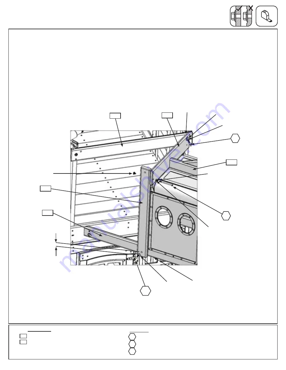
Place (510) Tunnel Right End tight to top of the Tunnel Assembly and centred pilot holes over (501) Tunnel
Top. With the bolt hole at the top loosely attach to (160) Crowsnest Top with 1 (G8) 5/16 x 2” Hex Bolt (with
lock washer and flat washer, t-nut previously installed). (fig. 51.6)
H:
Loosely attach (511) Tunnel Post to (490) Front Tunnel Support, making sure the bolt hole that measures
1-1/2” from the end is at the bottom of the board, with 1 (WB8) 5/16 x 2-3/8” Wafer Bolt (with flat washer and
t-nut). (fig. 51.6)
I:
Loosely attach other side of (510) Tunnel Right End to (511) Tunnel Post in the bottom hole with 1 (H8) 1/4 x
4-1/4” Hex Bolt (with lock washer, flat washer and t-nut). (fig. 51.6)
Step 51: Attach Tunnel Assembly to Fort
Part 3
Notice bolt
hole at top
501
Fig. 51.6
511
490
510
160
Wood Parts
1 x
Tunnel Right End FSC 5/4 x 6 x 23-11/16”
1 x
Tunnel Post FSC 2 x 4 x 31-1/4”
510
1-1/2”
511
1 x
5/16 x 2” Hex Bolt (5/16” lock washer & 5/16” flat washer)
1 x
5/16 x 2-3/8” Wafer Bolt (5/16” flat washer & 5/16” t-nut)
1 x
1/4 x 4-1/4” Hex Bolt (1/4” lock washer, 1/4” flat washer & 1/4” t-nut)
G8
G8
H8
WB8
WB8
H8
1/4”
T-Nut
5/16” Flat
Washer
5/16” Lock
Washer
5/16”
T-Nut
(hidden)
5/16” Flat
Washer
1/4” Lock
Washer
1/4” Flat
Washer
Make sure not
to over tighten
this bolt
130
Содержание F25668
Страница 146: ...NOTES 146 support cedarsummitplay com ...
Страница 147: ...NOTES 147 support cedarsummitplay com ...


