A:
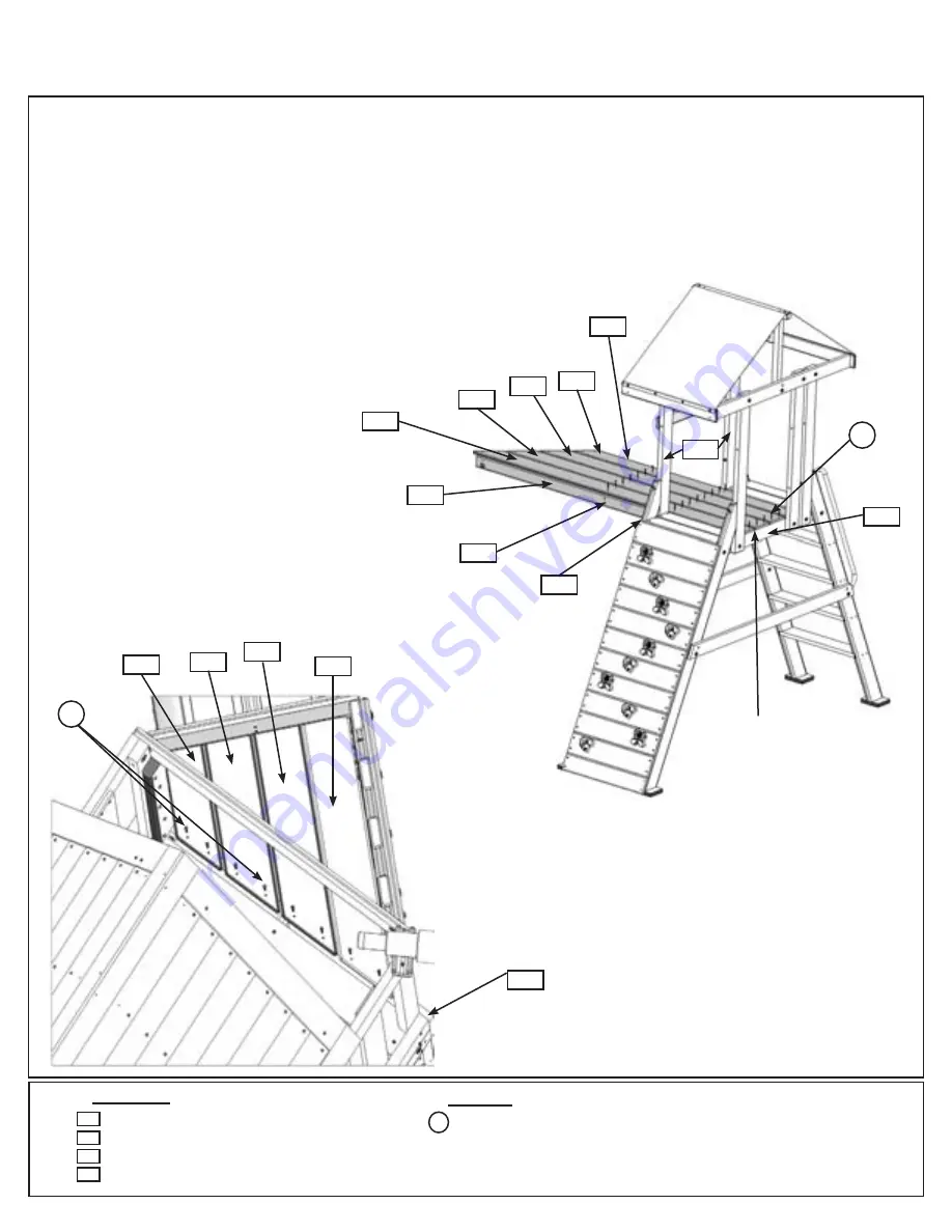
Starting at the Rock Wall side on the A Frame place (520) A Frame Floor A tight to (390) A Frame Uprights
and flush to the outside edge of the MK Wall (391) A Frame Floor Support. Follow with and evenly space (521)
A Frame Floor B, (522) A Frame Floor C and (523) A Frame Floor D. (523) A Frame Floor D must sit tight
to (390) A Frame Uprights on Access Wall side. Attach floor boards to both (391) A Frame Floor Supports,
(490) Front Tunnel Support, (492) Tunnel Joist and (491) Back Tunnel Support with 6 (S20) #8 x 1-3/8” Wood
Screws per floor board. (fig 52.1)
B:
Attach floor boards to (094) Floor End on the Main Fort with 2 (S20) #8 x 1-3/8” Wood Screws per board.
(fig. 52.2)
Step 52: Attach Tunnel Floor
391
Fig. 52.1
Fig. 52.2
Main Fort
(hidden)
521
520
(hidden)
x 2 per
board
523
522
Hardware
32 x #8 x 1-3/8” Wood Screw
Wood Parts
1 x
A Frame Floor A FSC 1 x 6 x 79-1/32”
1 x
A Frame Floor B FSC 1 x 6 x 73-19/32”
1 x
A Frame Floor C FSC 1 x 6 x 68-5/32”
1 x
A Frame Floor D FSC 1 x 5 x 62-23/32”
520
523
522
521
S20
S20
Rock Wall
Access
Ladder
MK Wall
521
520
523
522
094
391
491
492
490
390
(hidden)
Flush
x 6 per
board
S20
136
Содержание F25668
Страница 146: ...NOTES 146 support cedarsummitplay com ...
Страница 147: ...NOTES 147 support cedarsummitplay com ...


