N:
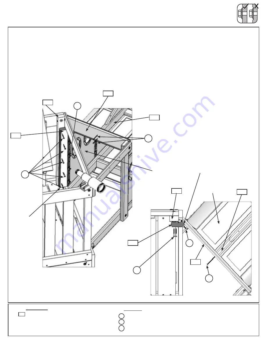
Attach (510) Tunnel Right End to (501) Tunnel Top with 2 (S4) #8 x 3” Wood Screws. (fig. 51.11)
O:
With the bevelled edge facing the Tunnel Assembly slide (513) Tunnel Corner Support in between Tunnel
Assembly and (2384) Crowsnest Post, making sure (513) Tunnel Corner Support sits tight to the floor boards
and (510) Tunnel Right End. Attach (513) Tunnel Corner Support to (161) Crowsnest Post with 5 (S7) #12 x 2”
Pan Screws. (fig. 51.11 and 51.12)
P:
Attach Tunnel Assembly to (513) Tunnel Corner Support with 4 (S10) #8 x 1” Pan Screws in the connector
tab holes. (fig. 51.11 and 51.12)
Step 51: Attach Tunnel Assembly to Fort
Part 6
2 x
#8 x 3” Wood Screw
5 x
#12 x 2” Pan Screw
4 x
#8 x 1” Pan Screw
S10
Hardware
S4
510
x 2
S10
S4
Fig. 51.12
Fig. 51.11
S7
510
161
501
513
501
161
S7
Top View
Wood Parts
1 x
Tunnel Corner Support FSC 2 x 4 x 23-5/8”
513
Tunnel
Assembly
Tunnel
Assembly
S10
x 4
x 5
S7
S4
x 4
513
Tight
Notice
bevelled edge
orientation
133
Содержание F25668
Страница 146: ...NOTES 146 support cedarsummitplay com ...
Страница 147: ...NOTES 147 support cedarsummitplay com ...


