


9
Electrode welding (MMA)
Electrode welding is used to weld most metals (different types
of steel, etc.) using coated rutilic and basic electrodes with di-
ameters ranging from Ø 1.6 mm to Ø 3,2 mm.
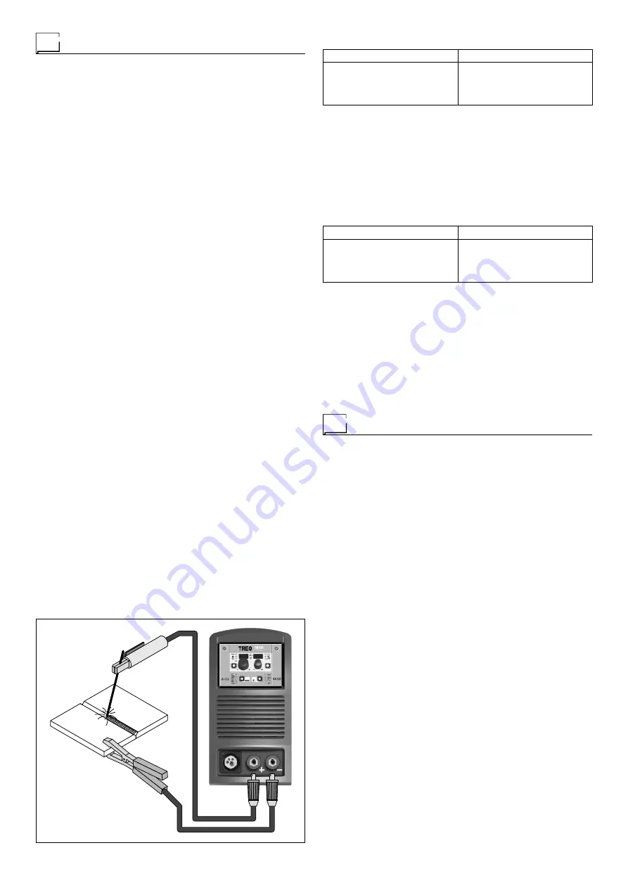
1) Connecting the welding cables (Fig. H):
Disconnect the machine from the mains power supply and
connect the welding cables to the output terminals (Posi-
tive and Negative) of the welding machine, attaching them
to the clamp and ground with the polarity specified for the
type of electrode being used (Fig. H). Always follow the
electrode manufacturer’s instructions. The welding cables
must be as short as possible, they must be near to one
another, positioned at or near floor level. Do not touch the
electrode clamp and the ground clamp simultaneously.
2) Switch the welding machine on by moving the power sup-
ply switch to
I
(Pos. 5, Fig. A).
3) Make the adjustments and select the parameters on the
control panel (for further information see the TX control
panel manual).
4) Carry out welding by moving the torch to the workpiece.
Strike the arc (press the electrode quickly against the met-
al and then lift it) to melt the electrode, the coating of which
forms a protective residue. Then continue welding by mov-
ing the electrode from left to right, inclining it by about 60°
compared with the metal in relation to the direction of weld-
ing.
PART TO BE WELDED
The part to be welded must always be connected to ground
in order to reduce electromagnetic emission. Much attention
must be afforded so that the ground connection of the part to
be welded does not increase the risk of accident to the user or
the risk of damage to other electric equipment. When it is nec-
essary to connect the part to be welded to ground, you should
make a direct connection between the part and the ground
shaft. In those countries in which such a connection is not al-
lowed, connect the part to be welded to ground using suitable
capacitors, in compliance with the national regulations.
WELDING PARAMETERS
Table 4 shows some general indications for the choice of elec-
trode, based on the thickness of the parts to be welded. The
values of current to use are shown in the table with the respec-
tive electrodes for the welding of common steels and low-grade
alloys. These data have no absolute value and are indicative
data only. For a precise choice follow the instructions provided
by the electrode manufacturer.
Table 4
WELDING THICKNESS (mm)
Ø ELECTRODE (mm)
1,2 ÷ 2
1,5 ÷ 3
3 ÷ 5
5 ÷ 12
1,6
2
2,5
3,2
The current to be used depends on the welding positions and
the type of joint, and it increases according to the thickness and
dimensions of the part.
The current intensity to be used for the different types of weld-
ing, within the field of regulation shown in table 5 is:
• High for plane, frontal plane and vertical upwards welding.
• Medium for overhead welding.
• Low for vertical downwards welding and for joining small pre-
heated pieces.
Table 5
Ø ELECTRODE (mm)
CURRENT (A)
1,6
2
2,5
3,2
30 ÷ 60
40 ÷ 75
60 ÷ 110
95 ÷ 140
A fairly approximate indication of the average current to use in
the welding of electrodes for ordinary steel is given by the fol-
lowing formula:
I = 50 × (Øe - 1)
Where:
I = intensity of the welding current
Øe = electrode diameter
Example:
For electrode diameter 4 mm
I = 50 × (4 - 1) = 50 × 3 = 150A
Maintenance
ATTENTION:
Cut off the power supply to the equipment be-
fore effecting any internal inspection.
TREO 1800 synergic
IMPORTANT:
Since the welding machines are fully electronic,
removing the dust that is sucked into the machine by the fans,
is of utmost importance.
In order to achieve correct functioning of the machine, pro-
ceed as described:
• Periodic removal of accumulations of dirt and dust inside the
equipment using compressed air. Do not point the jet of air
directly at the electrical parts as this could damage them.
• Periodical inspection for worn cables or loose connections
that could cause overheating.
• Make sure the air circuit is completely free of any impuri-
ties and that the connections are tight and free of any leaks.
In this connection, inspect the solenoid valve very carefully.
• Check the wire feeder rolls periodically and replace them
when wear impairs the regular flow of the wire (slipping etc).
TORCH
The torch is subjected to high temperatures and is also stressed
by traction and torsion. We recommend not to twist the wire and
not to use the torch to pull the welder. As a result of the above
the torch will require frequent maintenance such as:
• Cleaning welding splashes from the gas diffuser so that the
gas flows freely.
• Substitution of the contact point when the hole is deformed.
• Cleaning of the wire guide liner using trichloroethylene or
specific solvents.
• Check of the insulation and connections of the power cable;
the connections must be in good electrical and mechanical
condition.
FIG. H
Содержание TREO 1800 Synergic MIG-MAG
Страница 12: ...12 Electro topographical diagram 2101AB10...
Страница 14: ......
Страница 22: ......
Страница 42: ......


