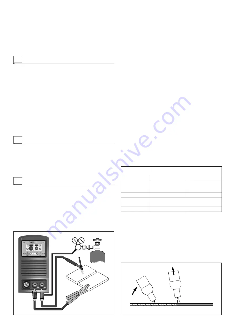
CEA TREO 1800 Synergic MIG-MAG Скачать руководство пользователя страница 8

8

FIG. F

To begin spot welding:

•  Place the gas guiding nozzle perpendicular on the workpiece 

to be spot welded.

•  Press the torch button to start the welding current and wire 

feed.

•  When the spot welding time expires (SPOT WELD TIME), 

the wire feed stops automatically.

•  When the torch button is pushed again a new welding cy-

cle starts.

•  Release the torch button.

  Interval welding (Stitch)

The substantial differences with the spot welding mainly con-

cern the adjustments that must be carried on the welding ma-

chine.

Use the control panel to select the interval welding mode and 

then make the changes to the related “Special functions - Fx” 

(for further information see the TX control panel manual), which 

allows the machine to do this specific type of welding.

To begin interval welding:

•  Press the torch button to start the welding current and wire 

feed.

•  At this point the welding machine automatically carries out 

a succession of welded portions (STITCH WELD TIME) fol-

lowed by a pause (STITCH WELD PAUSE), according to the 

times entered previously. This procedure stops automatically 

only when the TORCH BUTTON is released.

•  When the torch button is pushed again the torch begins a 

new interval welding cycle.

 Aluminium welding

To weld with aluminum wire proceed as follows:

•  Replace the drive roller with the appropriate for aluminum 

wire.

•  Use a torch with a 3m cable and a carbon Teflon sheath.

•  Set the pressure between the drive rollers at the minimum, 

by turning the screw provided.

•  Use argon gas at a pressure of 1,3 - 1,7 bar.

  TIG welding with “Lift”

In the TIG process welding is achieved by melting the two metal 

pieces to be joined, with the possible addition of material from 

the outside, using an arc ignited by a tungsten electrode. The 

“Lift” (TCS) type ignition used in TREO equipments makes it 

possible to reduce tungsten inclusions on ignition to a mini-

mum. The molten bath and the electrode are protected by and 

inert gas (for example, Argon). This type of welding is used 

to weld thin sheet metal or when elevated quality is required.

1)  Connecting the welding cables (Fig. F):

•  Connect one end of the gas hose to the gas connecter on 

the TIG torch and the other end to the pressure reducer 

on the inert gas cylinder (Argon or similar).

•  With the machine switched off:


- Connect the ground cable to the snap-on connector 

(positive).


- Connect the relative ground clamp to the workpiece or 

to the workpiece support in an area free of rust, paint, 

grease, etc..


- Connect the TIG torch power cable to the snap-on con-

nector marked - (negative).

2)  Switch the welding machine on by moving the power sup-

ply switch to 

I

 (Pos. 5, Fig. A).

3)  Make the adjustments and do the parameter settings on 

the control panel (for further information see the TX con-

trol panel manual).

4)  Open the gas cylinder and regulate the flow by adjusting 

the valve on the TIG torch by hand.

5)  Ignite the electric arc by contact, using a decisive, quick 

movement without dragging the tungsten electrode on the 

piece to be welded (“Lift” type ignition - Fig. G).

6)  The welder has a SWS “Smart Welding Stop” system for 

the end of TIG welding. Lifting up the torch without switch-

ing off the arc will introduce a slope down and it will switch 

off automatically.

7)  When you have finished welding remember to shut the 

valve on the gas cylinder.

Table 3 shows the currents to use with the respective elec-

trodes for TIG DC welding. This input is not absolute but is for 

your guidance only; read the electrode manufacturers’ instruc-

tions for a specific choice. The diameter of the electrode to use 

is directly proportional to the current being used for welding.

Table 3

Ø ELECTRODE 

(mm)

ELECTRODE TYPE

Current adjustment field (A)

TIG DC

Tungsten

Ce 1%

Grey

Tungsten

Rare ground 2%

Turchoise

1

10-50

10-50

1,6

50-80

50-80

2,4

80-150

80-150

3,2

150-250

150-250

FIG. G

2000HA86

Содержание TREO 1800 Synergic MIG-MAG

Страница 1: ...READ CAREFULLY 1020HA90B EN 12 2014 SN XN xxxxxx CEA COSTRUZIONI ELETTROMECCANICHE ANNETTONI S p A C so E Filiberto 27 23900 Lecco Italy Tel 39 0341 22322 Fax 39 0341 422646 Cas Post P O BOX 205 e ma...

Страница 2: ...knob for precise adjustment of the wire pressure that stays unvaried when the arms open and close Housing for coils of wire with max 200 mm 5 kg Possibility of fitting coils of wire up to max 300 mm...

Страница 3: ...d is exceeded a trip switch trips which protects the welding machine s internal components against dangerous overheat ing and prevents incorrect functioning of the machine for fur ther information see...

Страница 4: ...s hearing aids and similar equipment must consult their doctor before going near a ma chine in operation The equipment s installation environment must comply to the protection level of the frame i e I...

Страница 5: ...e mechanism Pos 6 Fig B Check that the drive roller Pos 4 Fig B has the diameter corresponding to the wire being used printed on the outer side Thread the wire into the central wire guide and into the...

Страница 6: ...hange polarity cable is connected to the positive pole 2 Welding 1 Open the moving cover and fit the coil of wire 2 Load the wire see the Loading the wire paragraph 3 Switch the welding machine on by...

Страница 7: ...torch Remove the gas guide and wire guide nozzles allowing the wire to flow freely during loading Remember that the contact tip must correspond to the wire diameter Push the torch push button or the...

Страница 8: ...reduce tungsten inclusions on ignition to a mini mum The molten bath and the electrode are protected by and inert gas for example Argon This type of welding is used to weld thin sheet metal or when el...

Страница 9: ...nly For a precise choice follow the instructions provided by the electrode manufacturer Table 4 WELDING THICKNESS mm ELECTRODE mm 1 2 2 1 5 3 3 5 5 12 1 6 2 2 5 3 2 The current to be used depends on t...

Страница 10: ...y connected to the plug and the supply switch 3 Check that the power fuses are not burned out or loose 4 Check whether the following are defective The switch that supplies the machine The plug socket...

Страница 11: ...ring that powers the various boards Check and if necessary replace the digital interface PCB or the control PCB No gas coming out of the torch Check and if necessary replace the solenoid valve or gas...

Страница 12: ...12 Electro topographical diagram 2101AB10...

Страница 13: ...B 17 Hall effect transformer 18 MMA torch 19 TIG torch 20 MIG MAG torch 21 Main transformer 22 Second ary diodes thermostat Colour key Ar Orange Az Sky Blue Bc White Bl Blue Gg Grey Gl Yellow GV Yello...

Страница 14: ......

Страница 15: ...ERE ATTENTAMENTE EN Spare parts list READ CAREFULLY CEA COSTRUZIONI ELETTROMECCANICHE ANNETTONI S p A C so E Filiberto 27 23900 Lecco Italy Tel 39 0341 22322 Fax 39 0341 422646 Cas Post P O BOX 205 e...

Страница 16: ...dex 4 352415 Pannello frontale Front panel 5 468185 Adesivo dinse Dinse sticker 6 403611 Attacco rapido Quick connection 7 239624 Cavo massa Ground cable 8 428110 Flangia Flange 9 434250 Tubetto guida...

Страница 17: ...ia Fixing bracket handle 17 435364 Interruttore alimentazione Mains switch 18 427895 Pressacavo completo di ghiera Cable clamp with lock ring 19 235960 Cavo alimentazione Mains cable 20 427866 Pressac...

Страница 18: ...bio polarit Change polarity protection box 23 240561 Meccanismo di trascinamento con motoriduttore Wire feed mechanism with motorgear 24 404913 Telaio metallico interno Internal metallic chassis 25 24...

Страница 19: ...Tubo gas Gas tube 32 353448 Isolamento laterale coperchio Cover insulation 33 486386 Motore ventilatore Fan motor 34 241266 Complessivo inverter di potenza Power inverter assembly 35 481954 Trasformat...

Страница 20: ...e arm 6 422923 Rullo di pressione 26 mm Feed roll 26 mm 7 487808 Vite di fissaggio M4x8 M4x8 Fixing screw 8 356956 Leva di pressione completa Complete pressure arm 9 676510 Spina elastica Pin pressure...

Страница 21: ...ei pezzi di ricambio Per la richiesta di pezzi di ricambio indicare chiaramente 1 Il numero di codice del particolare 2 Il tipo di impianto 3 La tensione e la frequenza che rileverete dalla targhetta...

Страница 22: ......

Страница 23: ...or s manual READ CAREFULLY CEA COSTRUZIONI ELETTROMECCANICHE ANNETTONI S p A C so E Filiberto 27 23900 Lecco Italy Tel 39 0341 22322 Fax 39 0341 422646 Cas Post P O BOX 205 e mail cea ceaweld com web...

Страница 24: ...N 11 2 WELDING MODE SELECTION 11 3 SPECIAL FUNCTIONS Fx SELECTION 12 4 PRE SETTING 12 5 WELDING 13 6 HOLD 13 Introduction This manual describes the functions and the manner of utilisation of the TX 18...

Страница 25: ...2T 2T LED switched on Pressing the TORCH TRIGGER starts the welding cycle which will stop when it is released FOUR STROKE 4T 4T LED switched on 1 Pressing and releasing the TORCH TRIGGER will start t...

Страница 26: ...ction Device VRD is a safety device that redu ces voltage It prevents voltages forming on the output terminals that may pose a danger to people Two tone LED off red green indicates enabling of the VRD...

Страница 27: ...ns the parameters normally used for set process functionality described in specific para graphs Then there is an independent parameter SPECIAL FUNCTIONS MENU SPC FnC that provides access to the SECOND...

Страница 28: ...MIG MAG SYN MIG MAG MAN TIG MMA 2T 4T CRA 2T CRA 4T SPOT 2T STITCH 2T FIRST LEVEL MENU MIG MAG process PRE GAS PrG 0 1s 0 0 2 0 s STARTING SPEED Sts 0 30 30 HOT START Hot 0 30 30 CRATER INITIAL CRATE...

Страница 29: ...T2 7 V 4 At this stage the partial reset or process default procedure has been completed successfully the parameters have been taken back to the factory values while any JOBS saved re main unaltered...

Страница 30: ...e seconds T2 7 V The procedure of calibration is carried out in 3 different phases 1 Calibration parameter SM1 MINIMUM SPEED Press and release the torch button then wait for the auto matic arrest of t...

Страница 31: ...2 MiG 010 011 Fe G3 Si 1 0 8 Ar 16 20 CO2 MiG 011 012 Fe G3 Si 1 1 0 Ar 16 20 CO2 MiG 012 015 Fe G3 Si 1 0 9 Ar 16 20 CO2 MiG 015 195 Fe rutil flux cored E71T GS 0 9 MiG 195 231 CrNi 308 G 19 9 LSI 0...

Страница 32: ...BURN BACK bub Regulates the length of the wire after wel ding The value indicated is a percentage variation in relation to the factory setting value Higher numbers correspond to more burning of the wi...

Страница 33: ...LED for a specific amount of time Once the welding has been terminated for about 15 seconds both the DISPLAYS should show the same values of the parameters during the welding In this phase the display...

Страница 34: ...ing in tracts is performed after the ignition of the arch after which the arch switches off automatically STITCH WELD PAUSE Srt Time of pause between one wel ding in tracts and another BURN BACK bub R...

Страница 35: ...for a specific amount of time Once the welding has been terminated for about 15 seconds both the DISPLAYS should show the same values of the parameters during the welding In this phase the displays s...

Страница 36: ...f low function at the start of the connection ARC FORCE ArC During the welding process it increases the current in percentage reducing in such a way the risk of fu sing the electrode to the piece Then...

Страница 37: ...ding Once 15 seconds have passed HOLD FUNCTION the TX con trol panel goes back to the PRESETTING phase 7 ACTIVATING THE VRD DEVICE The Voltage Reduction Device VRD is a safety device that redu ces vol...

Страница 38: ...L FUNCTIONS MENU SPC FnC that provides access to the SECOND LEVEL MENU SECOND LEVEL MENU See the Special Functions Menu SPC FnC paragraph 3 PRE SETTING Before welding it is possible to set the followi...

Страница 39: ...T2 To be able to choose another automatic welding point JOB that is free for saving the data simply turn one of the two EN CODER E1 E2 knobs until you reach the required point E1 E2 WARNING If all th...

Страница 40: ...its settings in the wel ding process it comes from keeping the SAVE MEM key T2 pressed for a duration of about 3 seconds 4 Acquire the parameters necessary for editing the JOB 5 Hold the SAVE MEM key...

Страница 41: ...istance dept Err E4 2 MIG SYN SPECIAL FUNCTION Fx WRONG NON automatic reset error Immediately contact technical assistance dept Err E4 3 MIG MAN SPECIAL FUNCTION Fx WRONG NON automatic reset error Imm...

Страница 42: ......

Отзывы: