35
2
.
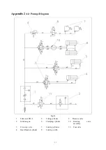
Air connection
:
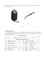
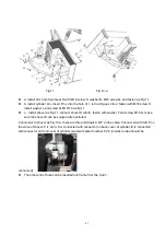
as Fig.2
,
connect tube C with D (the middle connector), the other side of tube is connected with
one way valve.
10.5.Operation
1
.
When
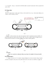
After tire is mounted, there is much space left between the rim and the tire as Fig.3, when normal inflating is not
workable, quick tire inflating is needed.
Much space left between
rim and
tire
Fig. 3
2
.
How
As
Fig.4-a
,
Let the mouth close to the edge of rim, hold valve body
F
by right hand, hold valve bush
E
by left
hand and push
E
as arrow direction, and you can hear “POP”, the groove is quickly inflated with high pressure air
from the tank, the rim and tire close touched as
Fig.4-b
, then normal tire inflating operation.
Fig. 4
NOTE
:
Please wear eye-glasses, ear-plugs and other personal protective equipment, when operating this
device
10.6.Maintenance
1
.
Regular check safe valve if it is normally working as
Fig.5-a
, when it reach at normal working air pressure
in the tank, hold needle
A
in the safe valve and pull it upward, and you can hear voice of deflation, it suggests the
Содержание CASC506
Страница 14: ...13 Fig 21 Fig 22 Fig 23...
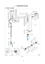
Страница 25: ...24 9 Exploded drawings 9 1 Column assembly Fig 34...
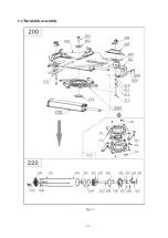
Страница 26: ...25 9 2 Turntable assembly Fig 35...
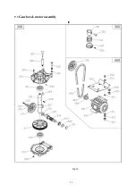
Страница 27: ...26 9 3 Gearbox motor assembly Fig 36...
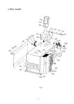
Страница 28: ...27 9 4 Body assembly Fig 37...
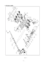
Страница 29: ...28 9 5 Pedal Assembly Fig 38...
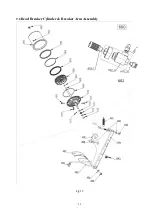
Страница 30: ...29 9 6 Bead Breaker Cylinder Breaker Arm Assembly Fig 39...
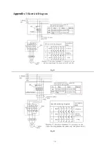
Страница 31: ...30 Appendix 1 Electrical Diagram Fig 41 Fig 42...
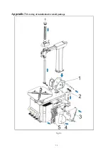
Страница 33: ...32 Appendix 3 Drawing of installation for small package Fig 44...
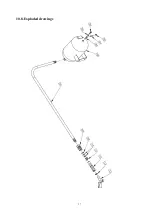
Страница 38: ...37 10 8 Exploded drawings...
Страница 50: ......


