background image

22


319


2009301


Worm Gear cover


1


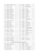
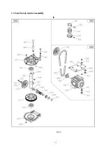
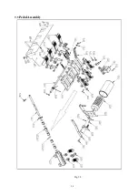
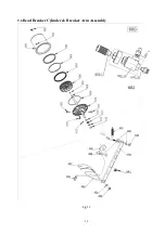
2012501 Parts of Motor Assembly (Fig.36)


400


2012501


Motor


1


406


6000192


Screw M8x35


4


401


4003101


Motor 220V 1.1KW


50HZ

standard 


1


407


6000139


Washer 8x22x2


8


4002801


Motor380V 0.75KW


50HZ

optional


408


6000134


Washer 10x20x2


3


4003201


Motor 110V 1.1KW


60HZ

optional


409


6000336


Nut M10


4


402


2012701


Motor Pulley


1


410


3003601


Washer


6


403


6000130


Screw M6*10


2


411


6000199


WasherФ8


4


404


6000237


Belt A660


1


412


6000127


Nut M8


4


405


2012601


Motor Support


1


413


4004444


Capacitor


1


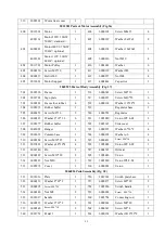
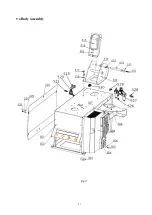
2065595 Parts of Body Assembly (Fig. 37)


501


2065596


Frame


1


516


6000348


Screw M6*10


1


502


2038701


Sign plate


1


517


6000187


Screw M10*55


6


503


3000101


Frame foot rubber


4


518


6000134


Washer 10*22*2


6


504


3005273


Robber buffer


1


519


Regulator base


1


505


6000253


Screw M6*16


5


520


4000701


Regulator


1


506


6000325


Washer 6*18*1.6


6


521


3005080


Union IPC 4-02


2


507


3005277


Rubber buffer


1


522


2065615


Side cover


1


508


2045001


Hanger


1


523


6000325


Washer 6*16*2


4


509


2065612


Column base


1


524


6000198


Washer φ6


4


510


6000184


Screw M10*25


4


525


6000431


Screw M6*16


4


511


2037401


Washer φ38*10*4


4


526


3005006


Union IPC 8-02


1


512


2065540


Pin


2


527


4004387


Oil mist


1


513


6000182


Screw M10*20


2


528


3005026


Union


1


514


6000123


Nut M10


2


529


3005010


Union IPL 8-02


1


515


3005272


Cover


1


530


4000901


Union


1


2064896 Pedal Assembly (Fig. 38)


531


2065616


Plate


1


556


2039301


Switch plate base


1


532


6000139


Washer 8*22*2


3


557


6000277


Screw M5*20


2


533


6000295


Screw M8*20


3


558


3005280


Switch handle


1


534


6000148


Nut M8


2


559


6000268


Screw  M4*16


1


535


2065617


handle


1


560


2065754


Connecting rod


1


536


6000325


Washer 6*12*2


2


561


6000244


Screw M8*20


1


537


6000348


Screw M6*10


2


562


6000349


Screw M3*8


2


540


2065752


Pedal 1


1


563


6000134


Washer Ф10*22*2


1


Содержание CASC506

Страница 1: ...Automatic tyre changer CASC506 Authorised representative CASTEX Anna Bednarz Ludwikowo 2C 85 502 Bydgoszcz www castex pl...

Страница 2: ...ent operation Do not put the equipment a place with high temperature or moisture or near the heating system water tap air humidifier or chimney Do not put the equipment near the window with sunlight P...

Страница 3: ...inflation system optional 30 11 Inflation box on the column optional 35 12 Pneumatic shovel optional 37 1 General Information 1 1 Usage The Machine is used for demounting mounting and inflating tires...

Страница 4: ...c specifications Voltage to choose RPM of turntable 6 7 n min 1 6 Description of Safety Signs To prevent accidents from occurring make sure to keep hands and other body parts away when fastening the m...

Страница 5: ...7 Position of Safety Signs Be careful in the area of tilting column The pressure of the compressed air should not exceed 10bar When inflating the tire The inflating gun pressure value should be 3 5 b...

Страница 6: ...reaker shovel M Return spring S Clamping cylinder assembly B Jaw flex pedal H Bead breaker arm N Locking handle T Hanger C Bead breaker pedal I Hanger O Mount demount head U Frame D Turn table control...

Страница 7: ...6 Fig 2 Accessories provided are shown in Fig 2 001 Inflating gun 002 Inflator tube 003 Tire lever 004 Jaw protector...

Страница 8: ...ust Clean it when necessary 3 2 Location The place to install the machine should be in accordance with safety regulations The machine should be installed in a place close to the main power source and...

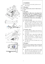
Страница 9: ...he top of hex column and install the plastic cover B back and tighten screw Fig 6 3 3 2 Install the column Use 6mm inner hexagon spanner to take off the screw B and washer C then take off the side cov...

Страница 10: ...essure 4 bar please do not adjust it by yourself 3 3 3 Install Hanger As fig 9 Insert the two heads into two 5 holes in the right side of column make sure I heads hook is upward Install side cover A a...

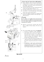
Страница 11: ...m included in the User s manual Otherwise the manufacturer will not be responsible for any accidents Operation test after power connected press pedal D Fig 13 turntable will turn clockwise This test i...

Страница 12: ...and tire bead where the bead breaker shoe goes in with industrial lubricant or thick soap solution Pay special attention to rotary direction marked on some flanges or tires Fit the tire on the rim of...

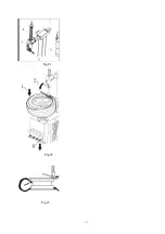
Страница 13: ...tch handle button N Fig 18 fix arm Press pedal A tilt the column Place the wheel on the turntable Depress pedal B For the asymmetric deep groove rim keep the narrow rim upward Fig 19 NOTE Different ty...

Страница 14: ...13 Fig 21 Fig 22 Fig 23...

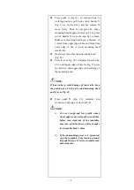
Страница 15: ...d press wheel as fig 22 1 until upper edge of wheel as Fig 23 press lever slowly until upper edge of wheel hang on the mounting head NOTE If inner tube to avoid damage of inner tube keep the position...

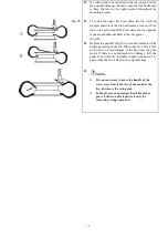
Страница 16: ...ck soap solution on the tire and the rim Put the bead on the rim with the left side upward press pedal A make column back to working position Fig 26 Check the coordination of mount demount head and ri...

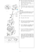
Страница 17: ...d to the rim groove Fig 29 Depress the pedal D Fig 22 to turn the turntable while keeping pressing on the tire When only 10 15cm is left slow down to avoid damage of the tire bead Stop the motor if th...

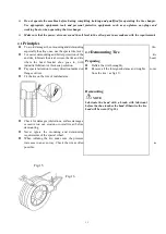
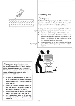
Страница 18: ...re Keep hands and the rest of human body away from tire The operator must adopt all the measures necessary in order to guarantee safe conditions 4 4 Inflating Tire Danger Inflating can be highly dange...

Страница 19: ...ct the power and keep the plug within the sight of the maintenance personnel and shut off compressed air push the air valve switch to Off position and depress pedal 16 for 3 or 4 times to bleed the re...

Страница 20: ...be held responsible for any use other than the designed purpose In case any damage occurs please contact your dealer or factory with the corresponding codes in the list SPARE PARTS LIST NO CODE Descr...

Страница 21: ...039201 Locking cylinder 2 126 2045101 Spring 2 171 2021201 Cylinder cover 1 127 2064804 Locking plate 1 172 3005191 O seal ring 1 128 3005039 Cover 1 173 3004101 Locking cylinder body 1 129 6000138 Wa...

Страница 22: ...6000233 Nut M6 4 2053301 Parts of Rotating Valve Assembly Fig 36 300 2053301 Complete rotating valve 1 303 3004601 O seal 59 5 3 1 3 301 2010901 Rotating valve core 1 304 2011001 Rotating valve casin...

Страница 23: ...w M6 16 5 520 4000701 Regulator 1 506 6000325 Washer 6 18 1 6 6 521 3005080 Union IPC 4 02 2 507 3005277 Rubber buffer 1 522 2065615 Side cover 1 508 2045001 Hanger 1 523 6000325 Washer 6 16 2 4 509 2...

Страница 24: ...3005067 Union IPB8 01 2 2065790 Parts of Bead Breaker Cylinder Fig 39 600 2065792 Complete bead breaker cylinder 1 607 3004301 O seal 20 2 4 1 601 2011201 Bead breaker cylinder barrel 1 608 2011501 P...

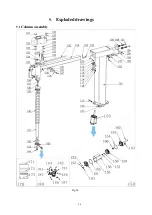
Страница 25: ...24 9 Exploded drawings 9 1 Column assembly Fig 34...

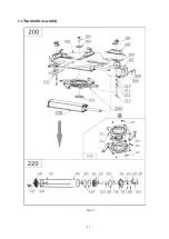
Страница 26: ...25 9 2 Turntable assembly Fig 35...

Страница 27: ...26 9 3 Gearbox motor assembly Fig 36...

Страница 28: ...27 9 4 Body assembly Fig 37...

Страница 29: ...28 9 5 Pedal Assembly Fig 38...

Страница 30: ...29 9 6 Bead Breaker Cylinder Breaker Arm Assembly Fig 39...

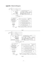
Страница 31: ...30 Appendix 1 Electrical Diagram Fig 41 Fig 42...

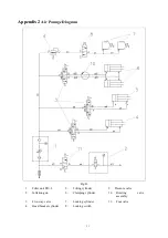
Страница 32: ...Diagram Fig 43 1 Filter unit FR L 5 Tilting cylinder 9 Pressure valve 2 Inflation gun 6 Clamping cylinder 10 Rotating assembly valve 3 Five way valve 7 Locking cylinder 11 Foot valve 4 Bead breaker c...

Страница 33: ...32 Appendix 3 Drawing of installation for small package Fig 44...

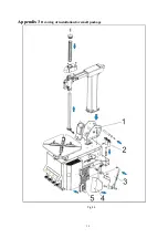
Страница 34: ...sed when there is much space left between tire and rim and normal tire inflating is not workable 2 This equipment is adopted hand pushing valve neatly easy to operate large displacement 3 The tube fea...

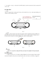
Страница 35: ...1 No Item No Item No Item A Valve D tube G Mouth B One way valve E Valve bush C Tank F Valve body 10 4 Installation Air connection Fig 2 1 Installation as Fig 2 With two M10 25 screw A Fasten tank B o...

Страница 36: ...alve body F by right hand hold valve bush E by left hand and push E as arrow direction and you can hear POP the groove is quickly inflated with high pressure air from the tank the rim and tire close t...

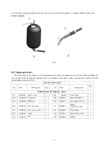
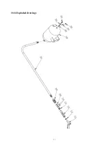
Страница 37: ...e contact your dealer or factory with the corresponding codes in the list SPARE PARTS LIST No Code Description Qty No Code Description Qty 1002154 Quick tire inflating Fig 6 701 4004001 Safety valve 1...

Страница 38: ...37 10 8 Exploded drawings...

Страница 39: ...38 11 Inflation box on the column optional Operated by pedal Inflating box Inflating mouth Pedal Air tube Air inlet...

Страница 40: ...ating box 1 D788 2064874 Valve bush 1 D782 3005005 ConnectorIPC8 01 1 D789 2064877 Spring 1 D783 3005337 Valve body 1 D790 2064876 Valve cap 1 D784 3005006 IPC8 02 1 D791 6000393 Screw M4 8 3 D785 300...

Страница 41: ...3005371 Protector 1 664 4004477 Valve 1 653 6000393 Screw M4 8 2 665 2066267 Pin 1 654 2066261 Shove handle 1 666 6000180 Pin 2 5 20 2 655 6000125 Screw M5 3 667 2066268 Connector 3 658 2066264 rod 1...

Страница 42: ...nect shovel D with E fasten with washer F and screw M16 G make sure the shovel D can be swayed after installed Connect air to shovel as Fig 12 a there are three terminals A B P on the valve Connect ai...

Страница 43: ...inder NOTE After connected and tested usual operation will be press down handle of shovel shovel will goes forward to frame side lift handle shovel goes toward to outside If not change position for A...

Страница 44: ...s intended purpose and with the requirements contained in the instruction manual Please read the detailed warranty conditions This warranty does not exclude or limit the buyer s rights arising from th...

Страница 45: ...Date signature and stamp The owner of the equipment submitting claims under the warranty is obliged to provide personal data in accordance with Art 23 section 1 point 3 of the Act on the Protection o...

Страница 46: ...ce with the order Contract specifications Pieces 1 2 3 4 5 Date Stamp and signature Receipt for the Guarantor of receipt of the warranty card NR Warranty Card No Serial Number Name Surname buyer s add...

Страница 47: ...46 In the case of a distance purchase this coupon must be sent back to the guarantor within 14 days from the date of purchase of the device...

Страница 48: ...ing under pressure or abandonment of maintenance or lack of cleaning CASTEX is not responsible for damage to the device caused during transport in the event that the transport is not ordered by CASTEX...

Страница 49: ...d and used in rooms where the air temperature is in the range from 8 to 25 degrees C 8 CASTEX reserves the right to refuse to provide free is services in the absence of a warranty card 9 In the case o...

Страница 50: ......
Отзывы: