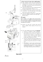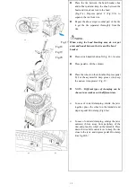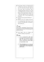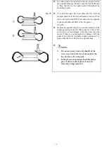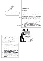
10
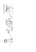
Fig.12
Fig.13
Fig.14
4.
Operation
NOTE
:
3.4
Power and Air Connections and Regulator
⚫
Before installation, check if the power source and the
compressed air are in accordance with the specifications on
the nameplate. Any electrical connection should be done by
the specially trained technician.
⚫
The power socket should be at a place within the sight of the
operator. The height should be between 24”
~
67”.
⚫
Grounding protection of power is needed for machine shell.
⚫
Air connection
:
Connect the inflation gun A to the coupling
located to the up of the air filter S (Fig.12).
⚫
Connect the compressed air supply to the coupling located
between the lubricator and the air filter S(as fig.12
,
direction of arrow
)
.
NOTE
:
The tire changer is not equipped with overload protection.
Please connect power according to the electric diagram included
in the User’s manual. Otherwise, the manufacturer will not be
responsible for any accidents.
⚫
Operation test: after power connected, press pedal D
(Fig.13), turntable will turn clockwise. This test is very
important.
⚫
F.R.L. :Filter, Regulator, Lubricator Assembly
(optional)
:
➢
See Fig. 14
:
1- Lubricator
;
2- Filter
;
3- Regulator.
➢
Adjust pressure: There is a button for the regulator 3.
When pulled up, the pressure can be increased or
decreased by turn it clockwise or counter-clockwise
(check the 4-Gauge). After adjusting the operation
pressure, press the button down to lock it.
➢
The Filter 2 works to filter the water and impurity in the
compressed air. When water and impurities run beyond
the red line, turn open the ejection valve 5 to release
them.
➢
The lubricator 1 is used to add a certain amount of
lubricant into gas for the moving parts in the cylinder
and regulator. Depress pedal C, 3
~
5 times, a drop of
lubricant will drop into the cup in the regulator. If it
doesn’t happen, the adjusting screw can be adjusted.
1
2
3
4
5
6
Содержание CASC506
Страница 14: ...13 Fig 21 Fig 22 Fig 23...
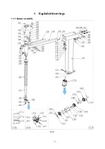
Страница 25: ...24 9 Exploded drawings 9 1 Column assembly Fig 34...
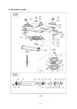
Страница 26: ...25 9 2 Turntable assembly Fig 35...
Страница 27: ...26 9 3 Gearbox motor assembly Fig 36...
Страница 28: ...27 9 4 Body assembly Fig 37...
Страница 29: ...28 9 5 Pedal Assembly Fig 38...
Страница 30: ...29 9 6 Bead Breaker Cylinder Breaker Arm Assembly Fig 39...
Страница 31: ...30 Appendix 1 Electrical Diagram Fig 41 Fig 42...
Страница 33: ...32 Appendix 3 Drawing of installation for small package Fig 44...
Страница 38: ...37 10 8 Exploded drawings...
Страница 50: ......


