background image

7 - MAINTENANCE

Alternator

NOTICE:

Do not use steam cleaning devices nor cleaning solvents to clean the alternator.

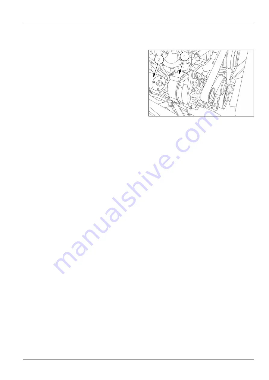
Have the alternator

(1)

checked by your Dealer.

LEEN12T0474AA

1

Starter motor - Check

Have the starter motor

(2)

checked by your Dealer.

NOTE:

Make sure the terminal protectors are correctly in-

stalled.

7-95

Содержание 580ST

Страница 1: ...Part number 47900121 3rd edition English October 2015 Replaces part number 47800831 OPERATOR S MANUAL 580T 580ST 590ST 695ST Tier 3 Tractor Loader Backhoe ORIGINAL INSTRUCTIONS ...

Страница 2: ... Safety rules Specific precautions to this machine 2 13 Safety rules Ductile iron 2 14 Loader attachment safety strut 2 15 Ecology and the environment 2 18 Hand signals 2 19 Safety signs 2 26 3 CONTROLS AND INSTRUMENTS ACCESS TO OPERATOR S PLATFORM Operator s platform 3 1 OPERATOR S SEAT Operator s seat 3 4 FORWARD CONTROLS Steering column 3 10 Front control panels 580T 580ST 590ST 3 12 Front cont...

Страница 3: ...Locking the loader attachment controls Specific to certain countries 3 55 BACKHOE ATTACHMENT CONTROLS Backhoe attachment controls 3 56 Backhoe attachment mechanical controls version 3 59 Backhoe attachment hydraulic controls version 3 70 CLIMATE CONTROLS Heating and air conditioning controls 3 76 Cab air louvers 3 81 4 OPERATING INSTRUCTIONS COMMISSIONING THE UNIT Before operating the machine 4 1 ...

Страница 4: ...ATIONS GENERAL INFORMATION Operating the machine in cold weather 6 1 Operating the machine in hot weather and high altitudes 6 2 Operating the machine in water 6 3 Lifting the machine 6 4 LOADER ATTACHMENT Organizing the job site 6 5 Transmission disconnect button 6 6 Operating the loader attachment 6 7 Loader attachment safety strut 6 11 Loader bucket Removal 6 14 Loader bucket Installation 6 15 ...

Страница 5: ...level 7 20 Hydraulic oil level 7 22 Fuel tank level 7 24 Engine coolant 7 26 Windshield washer fluid level 7 27 Check wheels and tires 7 28 Working attachments 7 29 Every 50 hours Fuel pre filter draining condensation 580ST 590ST 695ST 7 31 Tire pressure and condition 7 32 Air conditioning system 7 35 Door hinges 7 36 Working attachments 7 37 Every 250 hours Cab protection system 7 39 Seat and sea...

Страница 6: ...nd rear axle 7 83 Brake pedal lever Greasing 7 89 Hydraulic oil filter 7 90 Hydraulic oil 7 92 Hydraulic cylinders 7 94 Alternator 7 95 Every 2000 hours Engine coolant 7 96 As required Drive belt replacement 7 99 Turbocharger 7 99 Fuel system bleeding 7 101 Air conditioning compressor drive belt 7 102 Air prefilter cleaning 7 103 Air filter elements check 7 104 Air filter elements cleaning 7 105 W...

Страница 7: ...System 8 25 Cab 8 26 Air conditioning 8 27 9 SPECIFICATIONS Fluids and lubricants 9 1 Specifications 9 4 Noise and vibration levels 9 11 Buckets 9 12 Tires and wheels 9 13 Dimensions and performance 9 14 Maximum lifting loads 9 27 10 ACCESSORIES Mechanical backhoe bucket quick coupler 10 1 Hydraulic backhoe bucket quick coupler 10 3 Backhoe attachment auxiliary hydraulic tools 10 4 Manual auxiliar...

Страница 8: ......

Страница 9: ...NOT operate or permit anyone to operate or service this machine until you or the other persons have read and understand the safety operation and maintenance instructions in this manual Use only trained operators who have demonstrated the ability to operate and service this machine correctly and safely The information in this manual is provided on the basis of information that was available at the ...

Страница 10: ...ne for any purpose or in any manner other than as described in the manual signs or other product safety information provided with the machine These materials define the machine s intended use Consult an authorized dealer or CASE CONSTRUCTION on changes additions or modifications that can be required for this machine to comply with various country regulations and safety requirements Unauthorized mo...

Страница 11: ...aximum power of emission equipment radio telephones etc must not exceed the limits imposed by the national authorities of the country where you use the machine The electro magnetic field generated by the add on system should not exceed 24 V m at any time and at any lo cation in the proximity of electronic components The add on equipment must not interfere with the functioning of the on board elect...

Страница 12: ...ing up fluid levels greasing and replacing consumable articles such as lamp bulbs This manual does not contain all the information related to periodical service converting and repairs to be carried out by CASE CONSTRUCTION professional service per sonnel For some of the latter activities there may be a need for appropriate facilities technical skills and or tools which are not supplied with the CA...

Страница 13: ...1 GENERAL INFORMATION demonstrated the ability to operate and service the CASE CONSTRUCTION machine correctly and safely 1 5 ...

Страница 14: ... or assistance always give your Dealer the model and Product Identifi cation Number PIN of your machine and component concerned Machine Model PIN RAIL15TLB0177BA 1 580T and 580ST engine Fiat Powertrain Technologies FPT 72 kW 98 Hp F4GE9484C 580T or F4HE0484G 580ST PIN LEEN11T0339AA 2 1 6 ...

Страница 15: ...ST and 695ST engine Fiat Powertrain Technologies FPT 82 kW 111 Hp F4HE9484C 590ST or F4HE9484C 695ST PIN LEEN11T0339AA 3 Power shuttle transmission Model PIN LEEN11T0340AA 4 Powershift transmission Model PIN LEEN11T0341AA 5 1 7 ...

Страница 16: ...and Four Wheel drive 4WD models Additional components are required on the 4WD version Model PIN Ratio LEEN11T0342AA 6 Front axle Four Wheel Steer 4WS 695ST Model PIN Ratio LEEN11T0343AA 7 Rear axle Two Wheel Steer 2WS Model PIN Ratio LEEN11T0344AA 8 Rear axle Four Wheel Steer 4WS Model PIN Ratio LEEN11T0345AA 9 1 8 ...

Страница 17: ...oll Over Protective Structure ROPS and Falling Object Protective Structure FOPS Model PIN LEEN11T0346AA 10 Canopy Canopy with a certified Roll Over Protective Structure ROPS and Falling Object Protective Structure FOPS Model PIN LEEN11T0347AA 11 1 9 ...

Страница 18: ...perator s manual storage on the machine Keep the Operator s Manual in the storage compartment provided on the rear of the operator s seat The Opera tor s Manual must be available for use by all operators LEEN11T0064AA 1 1 10 ...

Страница 19: ...ntation The terms right hand left hand front and rear are used in this manual to indicate the sides of the machine as they seen from the operator s seat LEEN11T0030AA_2 1 1 Front side 3 Right hand side 2 Rear side 4 Left hand side 1 11 ...

Страница 20: ...1 GENERAL INFORMATION LEEN11T0031AA_2 2 1 Front side 3 Right hand side 2 Rear side 4 Left hand side 1 12 ...

Страница 21: ...r axle 8 Backhoe bucket 2 Operator s compartment Cab 9 Side shift carriage 3 Engine guard 10 Stabilizers 4 Loader arm 11 Fuel tank 5 Loader bucket 12 Front axle 6 Standard dipper or Inner sliding dipper 13 Hydraulic oil tank 7 Boom in line cylinder 14 Battery box NOTE Straight loader arm option is available 1 13 ...

Страница 22: ...8 Boom overlapping cylinder 2 Operator s compartment Cab 9 Side shift carriage 3 Engine guard 10 Stabilizers 4 Loader arm 11 Fuel tank 5 Loader bucket 12 Front axle 6 Standard dipper or Outer sliding dipper 13 Hydraulic oil tank 7 Backhoe bucket 14 Battery box NOTE Straight loader arm option is available 1 14 ...

Страница 23: ...ing cylinder 2 Operator s compartment Cab 9 Side shift carriage 3 Engine guard 10 Stabilizers 4 Loader arm 11 Fuel tank 5 Loader bucket 12 Front axle 6 Standard dipper or Outer sliding dipper 13 Hydraulic oil tank 7 Backhoe bucket 14 Battery box NOTE Straight loader arm option is available 1 15 ...

Страница 24: ...1 GENERAL INFORMATION 1 16 ...

Страница 25: ... that if not avoided could result in death or serious injury CAUTION indicates a hazardous situation that if not avoided could result in minor or moderate injury FAILURE TO FOLLOW DANGER WARNING AND CAUTION MESSAGES COULD RESULT IN DEATH OR SERIOUS INJURY Machine safety NOTICE Notice indicates a situation that if not avoided could result in machine or property damage Throughout this manual you wil...

Страница 26: ...become entangled in moving parts Wear protective equipment when appropriate DO NOT attempt to remove material from any part of the machine while it is being operated or while components are in motion Make sure that all guards and shields are in good con dition and properly installed before you operate the ma chine Never operate the machine with shields removed Always close access doors or panels b...

Страница 27: ... before you connect or disconnect fluid lines Stop the engine and remove the key before you connect or disconnect electrical connections Scalding can result from incorrect removal of coolant caps Cooling systems operate under pressure Hot coolant can spray out if you remove a cap while the sys tem is hot Allow the system to cool before you remove the cap When you remove the cap turn it slowly to a...

Страница 28: ...conditions At least once each day remove debris accumulation around moving components such as bearings pulleys belts gears cleaning fans etc More frequent cleaning of your machine may be necessary depending on the operating environment and conditions Inspect the electrical system for loose connections and frayed insulation Repair or replace loose or damaged parts Do not store oily rags or other fl...

Страница 29: ...ly at slow speeds and over level ground Avoid driving on highways or public roads Avoid quick starts or stops Avoid sharp turns Always wear correctly adjusted seat belts Keep door closed at all times Operator presence system Your machine is equipped with an operator presence sys tem to prevent the use of some features while the operator is not in the operator s seat Never disconnect or bypass the ...

Страница 30: ... is a special safety component of your machine DO NOT attach any device to the protective structure for pulling purposes DO NOT drill holes to the protective structure The protective structure and interconnecting components are a certified system Any damage fire corrosion or modification will weaken the structure and reduce your protection If this occurs THE PROTECTIVE STRUC TURE MUST BE REPLACED ...

Страница 31: ...f all fluids filters and containers in an environ mentally safe manner according to local laws and regula tions Check with local environmental and recycling cen ters or your dealer for correct disposal information Store fluids and filters in accordance with local laws and regulations Use only appropriate containers for the stor age of chemicals or petrochemical substances Keep out of reach or chil...

Страница 32: ... on surfaces that are not designated as steps or platforms Do not use the machine as a lift ladder or platform for working at heights Lifting and overhead loads Never use loader buckets forks etc or other lifting han dling or digging equipment to lift persons Do not use raised equipment as a work platform Know the full area of movement of the machine and equip ment and do not enter or permit anyon...

Страница 33: ...ck belts buckles retractors tethers slack take up system and mounting bolts for damage Replace all parts that have damage or wear Replace belts that have cuts that can make the belt weak Check that bolts are tight on the seat bracket or mounting If belt is attached to seat make sure seat or seat brackets are mounted securely Keep seat belts clean and dry Clean belts only with soap solution and war...

Страница 34: ...ocated to the right of the steer ing wheel On taking delivery of the machine study the fire extin guisher operating instructions The instructions are printed on the extinguisher NOTE Have the fire extinguisher inspected every year by a specialist MOLI12LBB0147AB 1 2 10 ...

Страница 35: ...ve equipment PPE is any equipment intended to be put on and kept by the worker for protection against one or more risks at work liable to threaten safety or health during work as well as all the complements or accessories intended for this purpose Wear PPE such as hard hat eye protection heavy gloves hearing protection protective clothing etc at all times working on the machines as instructed in t...

Страница 36: ...uld result in death or serious injury W0371A WARNING Fuel vapors are explosive and flammable Do not smoke while handling fuel Keep fuel away from flames or sparks Shut off engine and remove key before servicing Always work in a well ventilated area Clean up spilled fuel immediately Failure to comply could result in death or serious injury W0904A Do not fill the fuel tank completely to the top Allo...

Страница 37: ...ms up When using the backhoe Position the stabilizer pads for maximum stability Install a guard rail and warning signs to keep other per sons away from the machine if operating in an area with reduced visibility such as a building Place the direction control lever and the transmission in neutral and apply the parking brake before turning the operator s seat around to the backhoe position Ensure th...

Страница 38: ...ld cut drill repair or attach items to cast ductile iron parts on this machine Before you weld cut or drill holes on any part of this machine make sure the part is not cast ductile iron See your dealer if you do not know if a part is cast ductile iron The following items are examples of cast ductile iron parts There may also be other parts made of cast ductile iron that are not on the list below T...

Страница 39: ...or maintenance or servicing the unit Two Wheel Steer 2WS machines 580T 580ST and 590ST Engage the loader arm support strut 1 Empty the loader bucket 2 Raise the loader lift arms to the maximum height 3 Stop the engine and remove the starter switch key 4 Remove the split pin 1 and the lock pin 2 MOLI12LBB0260AB 1 5 Place the strut 3 on the cylinder rod and install the pin 2 and the split pin 1 back...

Страница 40: ...ove the starter switch key 4 Remove the split pins 1 and the safety strut 2 from the storage position on the loader arm Put the split pins back in place 5 Place the strut 2 on the cylinder rod and fasten it by means of the fastening flip 3 6 Lower the loader attachment until the safety strut is firmly against the cylinder MOLI12LBB0264AB 5 MOLI12LBB0265AB 6 Disengage the loader arm support strut 1...

Страница 41: ...2 SAFETY INFORMATION 4 Install the safety strut 2 in the storage position on the loader arm by means of the split pins 1 5 Start the engine and lower the loader attachment MOLI12LBB0264AB 8 2 17 ...

Страница 42: ...h all local legislation and available resources Do not allow coolant mixtures to get into the soil Col lect and dispose of coolant mixtures properly Do not open the air conditioning system yourself It contains gases that should not be released into the atmosphere Your CASE CONSTRUCTION dealer or air conditioning specialist has a special extractor for this purpose and can recharge the system proper...

Страница 43: ...t seeking the assistance of a flagman Make perfectly sure that you and the flagman understand the signals to be used The flagman must always keep out of the machine s working area The operator must always keep visual contact with the flagman stop the machine immediately if the contact is lost Start the engine MOLI12LBB0069AA 1 Stop the engine MOLI12LBB0070AA 2 Come to me MOLI12LBB0071AA 3 2 19 ...

Страница 44: ...2 SAFETY INFORMATION Move away from me MOLI12LBB0072AA 4 Go this far MOLI12LBB0073AA 5 Stop all and hold MOLI12LBB0074AA 6 Stop MOLI12LBB0075AA 7 2 20 ...

Страница 45: ...2 SAFETY INFORMATION Emergency stop MOLI12LBB0076AA 8 Raise load or bucket MOLI12LBB0077AA 9 Lower load or bucket MOLI12LBB0078AA 10 Raise load or bucket slowly MOLI12LBB0079AA 11 2 21 ...

Страница 46: ...2 SAFETY INFORMATION Lower load or bucket slowly MOLI12LBB0080AA 12 Turn machine left MOLI12LBB0081AA 13 Turn machine right MOLI12LBB0082AA 14 Roll back loader bucket MOLI12LBB0083AA 15 2 22 ...

Страница 47: ...2 SAFETY INFORMATION Dump loader bucket MOLI12LBB0084AA 16 Raise backhoe boom MOLI12LBB0085AA 17 Lower backhoe boom MOLI12LBB0086AA 18 Backhoe dipper in MOLI12LBB0087AA 19 2 23 ...

Страница 48: ...2 SAFETY INFORMATION Backhoe dipper out MOLI12LBB0088AA 20 Backhoe bucket dig MOLI12LBB0089AA 21 Backhoe bucket dump MOLI12LBB0090AA 22 Retract telescopic dipper If fitted MOLI12LBB0091AA 23 2 24 ...

Страница 49: ...2 SAFETY INFORMATION Extend telescopic dipper If fitted MOLI12LBB0092AA 24 2 25 ...

Страница 50: ...afety signs before you operate your machine Keep all safety signs clean and legible Clean safety signs with a soft cloth water and gentle detergent NOTICE Do not use solvent gasoline or other harsh chemicals Solvents gasoline and other harsh chemicals may damage or remove safety signs Replace all safety signs that are damaged missing painted over or illegible If a safety sign is on a part you or y...

Страница 51: ... items with an Asterisk are in the engine compartment NOTE The model shown is for reference only All models have the same placement of safety signs on the machine except some signs are specific to some model configurations Those specific safety signs are shown but may not apply to your machine 2 27 ...

Страница 52: ...ab option Sit in the operator seat face the backhoe and it is on the left hand side of the window Canopy option Sit in the operator seat face the backhoe and it is on the left hand side of the fender Quantity 1 Part number A 47937191 580T and 580ST with in line cylinder boom B 84236340 580T and 580ST with overlapping cylinder boom C 84261481 590ST D 84261761 695ST A RAIL15TLB0667AA 2 B LEEN11T0040...

Страница 53: ...to comply will result in death or serious injury Location On the right hand and left hand sides of the backhoe boom On the right hand and left hand sides of the loader arms Quantity 4 Part number 85804331 LEEN11T0454AA 7 4 Warning Do not use Ether WARNING Explosion hazard Do not use ether Failure to comply could result in death or serious injury Location On the fixed hood Quantity 1 Part number 86...

Страница 54: ...hift stabilizer frame Center pivot machines Back of the machine on the right hand and left hand sides of the swing tower Quantity 4 Part number 87051987 87051987A 11 8 Warning Crush hazard This sign warns you to keep a minimum safety distance between your feet and the moving stabilizers Failure to comply could result in death or serious injury Location Side shift machines Back of the machine on th...

Страница 55: ... in raised position Failure to comply could result in death or serious injury Location On the safety strut on the left hand side of the machine Quantity 1 Part number 85804325 LEEN11T0451AA 15 12 Noise level This sign shows the value in decibel of the external noise level LWA of machine as guaranteed by the Manufacturer 580T 580ST 102 dB A 590ST 695ST 103 dB A Location Cab version On the left hand...

Страница 56: ...he hydraulic tank Quantity 1 Part number 85804341 LEEN11T0450AA 18 15 Battery hazard WARNING Explosion hazard Run over hazard Read procedure in Operator s Manual before jump start or service to avoid injury Failure to comply will result in death or serious injury Location Right hand side of the machine on the battery compartment Quantity 1 Part number 85804330 LEEN11T0448AA 19 2 32 ...

Страница 57: ...2 SAFETY INFORMATION LEIL12TLB00003I 20 NOTE Cab version safety signs shown Review the safety sign description in the following pages for sign locations on models with a canopy 2 33 ...

Страница 58: ...f the cab Canopy location On the underside of the instrument panel cover 47489575 21 Quantity 2 Part number 47489575EN 47489579FR 47489581ES 47489589PT 47489602TR 47489659RU 2 Warning Loader arm rated lift capacity chart WARNING Tip hazard Lifting too heavy a load can cause machine to tip or loss of operator control Failure to comply could result in death or serious injury Location Cab version Sit...

Страница 59: ...t from the ground is approximately identified on the safety sign of your machine When transporting the machine be sure to know the distance between the ground and the highest point of the machine NOTE This safety sign is specific to certain countries Location Cab location Sit in the operator s seat face the loader arm and it is on the upper right hand side of the front window Canopy location Sit i...

Страница 60: ...y 1 Part number 85813494EN 85813493FR 85813497ES 85813502PT 87324360TR 84122000RU 6 Fire extinguisher The CASE CONSTRUCTION recommends that you keep a fire extinguisher on your machine at all times A fire extinguisher is available from your dealer Have a fire equipment representative inspect the fire extinguisher annually Location Sit in the operator s seat face the loader arm and it is on the rig...

Страница 61: ... of the instrument panel cover Quantity 2 Part number 47489570 LEEN11T0441AA 32 10 Seat belt This sign reminds you to wear your safety belt at all times Avoid the risk of being ejected from the operator s compartment in the event that the machine turns over Cab location Sit in the operator s seat face the loader arm and it is on the right hand post of the cab Canopy location On the underside of th...

Страница 62: ...re to comply could result in death or serious injury Location Inside the cab face the backhoe and it is on the right hand control tower Quantity 1 Part number 47489693 47489693 36 Maintenance in progress tag Do not operate It is mandatory for maintenance personnel to apply this maintenance tag to the machine when servicing the machine Never attempt to start or operate the machine when the maintena...

Страница 63: ...ING Fall hazard Clean the steps and access handles to remove all traces of grease oil mud and ice in winter Failure to comply could result in death or serious injury W0139A Entering the machine 1 Canopy machines proceed to Step 5 2 Use the starter key to unlock the cab door 3 Push the lock 1 button completely inwards and pull the handle 2 4 Fully open the door so that the door grab handle is withi...

Страница 64: ...ecure the window position NOTICE When opening or closing windows always hold them firmly until they are completely locked in position Hold partially open Raise the handle 1 and push it outwards and down wards to lock the window in a partially opened position Hold fully open 1 The window must be in the closed position raise the handle 1 to the horizontal position and then tilt it rear wards to dise...

Страница 65: ... 2 Push the window outwards and upwards simultane ously to open it until it engages with the locking device NOTICE Make sure that the window is secure Closing 1 Release the latches 2 and tilt into lower position with the handles 2 Lock the window with the locks 1 MOLI12LBB0136AB 6 MOLI12LBB0137AB 7 3 3 ...

Страница 66: ... Roll Over Protective Structure ROPS cab for your protection The seat belt can help ensure your safety if it is properly used and maintained Never wear a seat belt loosely or with slack in the belt system Failure to comply could result in death or serious injury W0376A To operate the machine correctly with maximum efficiency and comfort check that the operator s seat and its adjust ment controls a...

Страница 67: ...t back to obtain the desired position and then release the lever Swing Release the seat using lever 5 and swing it round Re lease the lever and make sure that the seat locks in place Combined height and weight adjustment Adjustment may be made to suit the operator s size Turn the control 6 setting Seat fore and aft adjustment Hold the lever 7 in raised position slide the seat until the desired pos...

Страница 68: ...t position and then lower the armrest LEEN11T0083AA 3 Cushion angle adjustment Lift the handle 2 up and move the cushion to the desired position Release the handle to lock the cushion in place Lift up on the handle 3 Move the seat to the desired angle Release the handle to lock the cushion angle LEEN11T0459AA 4 3 6 ...

Страница 69: ...on the socket 5 LEEN11T0460AA 5 Seat back angle adjustment To adjust the seat back angle hold the lever 6 rearward move the seat back to obtain the desired position and then release the lever Swing Release the seat using lever 7 and swing it round Re lease the lever and make sure the seat is locked correctly in place LEEN11T0461AA 6 3 7 ...

Страница 70: ...N11T0087AA 7 Pneumatic version Lower the lever 9 to reduce the rigidity of the suspension Raise the handle to increase the rigidity of the suspension The indicator 10 must be green when the operator is sitting on the seat Seat fore and aft adjustment Hold the lever 11 in raised position slide the seat until the desired position is reached and then release the lever LEEN11T0464AA 8 3 8 ...

Страница 71: ...3 CONTROLS AND INSTRUMENTS Lumbar support adjustment Turn the knob 12 to obtain good back support from the seat back LEEN11T0088AA 9 3 9 ...

Страница 72: ... power steering never hold the steering wheel against either of the steering stops Failure to observe this precaution may result in damage to the steering system components NOTICE If the steering hose broke and the machine could not be steered stop the machine immediately Contact your CASE CONSTRUCTION Dealer for further assistance In the event of loss of power steering due to engine failure the m...

Страница 73: ...ng brake Failure to comply could result in death or serious injury W1032A The angle of the steering column can be varied through an approximate range of 10 to 20 Adjustment is by release of the foot pedal 1 at the base of the column Apply a light pressure to this pedal and position the steering column to suit your needs With the column in the desired position release the foot pedal which will lock...

Страница 74: ...control lamp off condition with blocked valves Second position control lamp on by pressing the side with the symbol the valves are released 5 Rotating beacon switch This switch is used to turn the rotating beacon on or off 6 Roll over protection switch Optional This switch is used to engage or disengage the roll over protection device When the operator is about to start working with the backhoe at...

Страница 75: ...lection switch Powershift transmission In situations where manual gearshifting up or downshift is required the automatic gearshift of the powershift transmission can be overridden with this switch When the manual mode is no longer required place the switch back to the OFF position to return to automatic gearshifting NOTE Changing gears up or down must always be done using the powershift transmissi...

Страница 76: ...trol lamp off condition with blocked valves Second position control lamp on by pressing the side with the symbol the valves are released 4 Steer mode switch This switch has a locking cover and is used to select Road 4 wheel steer or Crab steer This switch has three positions Position a Road Position b 4 wheel steer Position c Crab steer NOTICE Before undertaking any road travel select Road mode an...

Страница 77: ...ating the loader attachment It reduces forward and rearward pitching when moving rearwards or forwards and when carrying loads at the same time increasing productivity and operator comfort It also reduces impact forces to the machine during operation Do not use this system while operating the load attachment 8 Manual mode selection switch Powershift transmission In situations where manual gearshif...

Страница 78: ...e locked together for road travel This ensures uniform brake application and maximum stopping ability Failure to comply could result in death or serious injury W0308A Located under the steering wheel these two pedals 1 are equipped with a system 2 which enables them to be locked together or unlocked This enables the machine either to be braked pedals locked by pressing either of the pedals or to b...

Страница 79: ...controls 580ST 590ST LEEN11T0017FA 1 1 Gearshift lever It is possible to select four forward and four rearward travel gears with this lever 2 Transmission disconnect button on gearshift lever Prior to gearshifting press and hold this switch se lect the desired gear with the gearshift lever and re lease the switch to reengage transmission 3 Direction of travel lever The movement of this lever from ...

Страница 80: ... A device for transmission disconnection is activated by pushing button 2 placed on the gearshift lever 1 or by pushing button 5 placed on the loader attachment control lever LEEN11T0045AA 2 Gearshift lever The gearshift lever 1 is used to select any of the four gear ratios The transmission disconnect button 2 is depressed and held as the lever is shifted from one gear to another The button is the...

Страница 81: ...th a neutral lock to prevent an accidental engagement of the trans mission With this design the power shuttle lever moves through a T slot to the forward or reverse positions NOTICE When operating at low environmental temper atures with cold transmission oil allow the oil to warm up before attempting to shift the power shuttle lever The transmission can be shifted normally after the oil warms up N...

Страница 82: ...lever knob 1 is easy to operate NOTICE Do not use the disconnect switch control down hill because excessive speed may cause loss of control personal injury or the failure of transmission To make upward gear ratio changes simply depress and hold button 2 on the gearshift lever 1 while shifting the same from one gear ratio to another When the desired gear ratio has been selected release the button a...

Страница 83: ...fficient engine power to operate the loader attachment however to prevent the transmission from overheating either reduce the load on the machine or select a lower gear ratio NOTICE Operating at a stall for more than 20 seconds can cause the transmission to overheat and can possibly damage the transmission If the transmission overheats the needle 3 reaches the red field Shift both the power shuttl...

Страница 84: ...y turning the knob instead the following gears are selected 1 1st gear 2 2nd gear 3 3rd gear 4 4th gear 2 Kickdown switch If the machine is in second gear and it is necessary to shift to the first gear to work with the loader at tachment activating the kickdown switch to a lower ration allows the machine to instantly shift from sec ond to first gear When the reverse travel is activated transmissio...

Страница 85: ...n disconnection The disconnect feature is useful when loading for exam ple when pushing the loader into a pile and you have sufficient dirt in the bucket press the disconnect switch 3 which disengages the transmission and allows the full power of the engine to be directed to the hydraulic oil pump Disconnect is available in 1st and 2nd gear NOTE Transmission disconnect is selectable when the machi...

Страница 86: ...Position 2 The right hand direction indicators and the di rection indicator lamp on the side instrument cluster flash at the same speed LEEN11T0041AA 1 Position 3 Light switch in low beam position Push the lever downwards to turn on the main beams and the cor responding indicator lamp LEEN11T0042AA 2 Position 4 Turn the knob of the handle counterclockwise to activate the front windshield wiper 0 S...

Страница 87: ...e fully aware of the location and the function of each control Failure to comply could result in death or se rious injury W0226A Located on the right of the operator s seat with seat in loader attachment position this switch has four positions Position 1 Not used Position 2 Stop Position 3 Contact the audible alarm sounds Position 4 Start LEEN11T0037AA 1 NOTE This key can be used to lock the cab d...

Страница 88: ... be immobilized Raise the lever to immobilize the machine wheels braked In this position the indicator lamp on the in strument panel turns on Press and hold down the push button on the tip of the lever and then lower the lever to release the brakes wheels are free to rotate In this position the lamp on the instrument panel is out If the gear is engaged when the parking brake is activated it will a...

Страница 89: ...ighways ATTENTION If you use the backhoe attachment or if you are carrying out maintenance operations use the engine accelerator lever The use of the lever for any other oper ation can cause accidents LEIL12TLB0002AA 1 Engine accelerator knob 580ST 590ST 695ST The knob 1 enables the engine speed to be increased or decreased Clockwise to increase the speed Counter clockwise to decrease the speed AT...

Страница 90: ... lamp off Second position by pressing the symbol side the side work lights turn on at the same time control lamp on 4 Backhoe attachment locking switch The switch is used to lock or unlock the backhoe at tachment safety hook in preparation for road travel 5 Rear work light switch This switch has three positions The first position is OFF control lamp off Second position by pressing the symbol side ...

Страница 91: ...e of the symbol to shift the backhoe attachment to the left side of the track track sides are referred to the travel direction of the machine 11 Horn switch only models with mechanical backhoe controls This switch operates the warning horn 12 Backhoe attachment quick coupler switch Optional Press both switches to activate the quick coupler of the backhoe attachment Press on the 2 switches to unloc...

Страница 92: ...safety hook in preparation for road travel 5 Rear work light switch This switch has three positions The first position is OFF control lamp off Second position by pressing the symbol side first click the outer rear work lights are turned on con trol lamp on Third position by pressing the symbol side again second click the inner rear work lights are turned on too control lamp on 6 Side instrument cl...

Страница 93: ...oe attachment to the left side of the track track sides are referred to the travel direction of the machine 10 Horn switch only models with mechanical backhoe controls This switch operates the warning horn 11 Backhoe attachment side shift carriage locking switch Side shift version It allows locking control lamp on or unlocking control lamp off the sliding carriage the backhoe attachment is mounted...

Страница 94: ...ptional The rotating beacon 1 should be placed on the cab roof and the cable connected to one of the 12 V sockets over the door on each side of the machine NOTICE The rotating beacon must be installed and op erated when undertaking road travel LEEN11T0081AA 1 3 32 ...

Страница 95: ...trical work before connecting the cable Failure to comply could result in death or se rious injury W0137A The battery master switch 1 is located in the battery com partment and is used to completely disconnect the battery from the electrical system When the battery master switch has an inclination of 45 2 the circuit is disconnected To disconnect the circuit place the battery master switch in the ...

Страница 96: ...mp turns on when the parking brake lever is in the raised position wheels braked 9 AIR FILTER RESTRICTION LAMP This warning lamp turns on when the air filter element needs to be cleaned or replaced 10 BATTERY CHARGE INDICATOR This indicator shows the state of charge of the bat tery At normal charge the needle should be in the grey area If the needle is in the left red area this shows that the batt...

Страница 97: ...rmal the needle is in the green zone If the needle is in the red area change down to a lower gear If the needle still re mains in the red area stop the machine travel place the gearshift lever and the direction of travel control lever in the neutral position and leave the engine run ning at 1000 rpm If this operation does not enable the oil temperature to be reduced check the gear box oil level an...

Страница 98: ...d and phased 6 Road steer 2WS indicator switch This lamp turns on when 2 wheel steer mode is selected and phased 7 Crab steer indicator lamp This lamp turns on when crab steer mode is se lected and phased NOTE If the three lamps 5 6 and 7 turn on at once this indicates that there is a problem with the electrical circuit Consult your Dealer 8 Engine oil pressure warning lamp This warning lamp turns...

Страница 99: ...ight red area this indicates excessive battery charge which may cause damage to the battery 18 Diagnostics display With this display it is possible to visualize the vari ous data of diagnostics The service hours are also indicated 19 Tachometer The tachometer shows the engine speed in revo lutions per minute The figures indicated must be multiplied by 100 Each intermediate mark shows a value of 10...

Страница 100: ... used to confirm the selected choices LEEN11T0036AA 2 Using the display switches you will be able to scroll through the following battery voltage backhoe loader hours setup Features adjustable during setup backlighting dimming and contrast control maintenance service interval customization storage of error codes glow plugs presence it is possible to select or dese lect the glow plugs function low ...

Страница 101: ...3 CONTROLS AND INSTRUMENTS Setup menu LEIL12TLB00006I 1 3 39 ...

Страница 102: ...ighting The interval can be set between 50 h and 500 h in steps of 50 0 0 50 100 150 200 250 300 350 400 450 500 The 0 0 setting turns the light maintenance feature off Heavy maintenance The hours shown will be the hours when heavy mainte nance is required not the standard hours displayed by the hourmeter Amber colored lighting The interval can be set between 50 h and 500 h in steps of 100 0 0 500...

Страница 103: ...TS Display function When the hourmeter reaches the light service interval MAIN SCREEN 3 Seconds LIGHT 800 3 500 AMBER When the hourmeter reaches the heavy service interval MAIN SCREEN 3 Seconds HEAVY 800 3 1000 3 seconds 3 41 ...

Страница 104: ...erator s Manual can be stored LEEN11T0064AA 1 Document storage box Under the cab roof there is a document storage box 1 where any documents can be stored LEEN11T0063AA 2 Operator s compartment light This light is mounted on the roof The light turns on when the door opens Press OFF to turn off the light when the door is open press ON to turn on the light when the door is closed LEEN11T0065AA 3 3 42...

Страница 105: ...ush up the latch 2 to roll up the sun visor LEEN11T0066AA 4 Auxiliary 12 V socket An auxiliary 12 V power socket 1 is located on the cab s left hand post LEEN11T0067AA 5 Radio compartment Optional On the cab roof there is a compartment 1 where the radio is installed the radio is provided on demand LEEN11T0068AA 6 3 43 ...

Страница 106: ...ir This reservoir 1 is located on the left hand side of the cab and has two electric pumps controlled by a switch or by the lever for the direction indicators main beams front windshield wiper and washer NOTE In cold weather use a windshield washer with low temperature capability NOTICE Never operate the windshield washer when the reservoir is empty since this may damage the electric pumps LEEN11T...

Страница 107: ...ne latch to release the lock 2 3 Use the engine hood lift handles 4 lift and rotate the hood 3 into the fully open position NOTICE Before undertaking any road travel make sure the engine guard is properly locked Close and lock the engine hood figures in reverse order 1 Push the hood down in to the closed position 2 Push the engine latch 2 down into the lock position 3 Insert the key 1 and turn clo...

Страница 108: ...intenance procedure LEEN11T0074AA 13 Fire extinguisher DANGER Fire hazard Always have a fire extinguisher on or near the machine Keep the fire extinguisher in good condition through routine maintenance and service according to the manufacturer s instructions Failure to comply will result in death or serious injury D0006A The fire extinguisher 1 is located to the right of the steer ing wheel On tak...

Страница 109: ...ave access to the engine data and to detect possible faults when connected to the electronic service tool LEEN11T0078AA 16 Coded anti theft switch Optional Located on the right hand console the switch 1 has a red flashing lamp and makes it possible to disengage the engine anti start device using the special electronic key If the electronic key is not inserted and you try to start the machine the d...

Страница 110: ...and and left hand rearview mirrors 1 are correctly adjusted before undertaking any travel LEEN11T0080AA 18 LOADER ATTACHMENT CONTROLS Loader attachment control lever 1 Loader attachment control lever 2 Transmission disconnect button 3 Horn button LEEN11T0051AA 1 3 48 ...

Страница 111: ... out the following pro cedure Before engaging the differential lock make sure neither rear wheel is spinning freely To engage the differential lock press switch 1 To disengage the differential lock release switch 1 When activated the differential lock places both rear wheels into direct drive This control is therefore useful to stop a possible slip of one of the rear wheels The lock remains engage...

Страница 112: ...with slack in the belt system Never wear the belt if it is twisted or pinched between the seat struc tures Failure to comply could result in death or se rious injury W0142A With standard loader bucket Located on the right of the steering wheel this nine posi tion lever operates all the loader attachment controls The speed of movement of each control depends on the angle to which the lever is tilte...

Страница 113: ...as the lever is released it automatically returns to the neutral position 0 and the attachment remains in the position where it was when movement stopped LEEN11T0089AA 1 Raising the loader attachment With the lever in position 1 the attachment rises LEEN11T0090AA 2 Lowering the loader attachment With the lever in position 2 the attachment lowers LEEN11T0091AA 3 3 51 ...

Страница 114: ...rate the lever NOTE In this position the lever does not automatically return to neutral when it is released It is necessary to move it manually LEEN11T0092AA 4 Filling the loader bucket With the lever in position 4 the bucket rolls back fills LEEN11T0096AA 5 Dumping the loader bucket With the lever in position 5 the bucket rolls forward dumps LEEN11T0097AA 6 3 52 ...

Страница 115: ... return to loader bucket filling With the lever in position 6 the attachment lowers and simultaneously the bucket places itself to the digging po sition NOTE It is possible to adjust the tilt angle for bucket filling LEEN11T0098AA 7 3 53 ...

Страница 116: ... the switch The standard position of the switch is with the open U shape pointing upwards In this configuration the switch will automatically spring back to the neutral position when released from any position To set the detent position to the bucket open position it is necessary to remove the top of the switch rotating it by 180 Remove the screw 2 of the roller 1 using a small Phillips screwdrive...

Страница 117: ...l lever is used to lock the attachment controls To lock the controls remove the pin from its housing and install it in the specially provided hole in the console NOTICE Before leaving the operator s compartment un dertaking any road travel or working with the backhoe at tachment place the pin in locking position LEEN11T0180AA 1 3 55 ...

Страница 118: ...xpected machine movement Before you turn the operator s seat around to the backhoe operation position shift the direction con trol lever and the transmission to neutral and apply the parking brake Failure to comply could result in death or serious injury W0194A NOTE The instruments represented may not exactly correspond to the instruments on your machine NOTE Before using the backhoe controls make...

Страница 119: ...the stabilizers to the ground so that the rear tires are just off the ground 6 Place the backhoe attachment side shift carriage lock switch 1 in the OFF position 7 Move the boom all the way towards you to relieve pressure on the boom lock 3 8 Press the button on the backhoe transport control lever 2 and move forward to disengage the boom 9 If applicable remove the extendable dipper lock pin and pl...

Страница 120: ...on 4 Turn the seat into the backhoe operation position 5 Lower the stabilizers to the ground so that the rear tires are just off the ground 6 Place the backhoe attachment side shift carriage lock switch 1 in the OFF position 7 Press the switch 2 to unlock the boom from the trans port position 3 8 If applicable remove the extendable dipper lock pin and place it in the storage position LEEN11T0311AA...

Страница 121: ...zer As soon as the lever is released it automatically returns to the neutral position 0 and the right hand stabilizer stops raising or lowering Position 1 The right hand stabilizer lowers Position 2 The right hand stabilizer rises NOTE To raise or lower the two stabilizers at the same time operate the two levers simultaneously NOTICE Before machine travel or before using the loader attachment make...

Страница 122: ...ons Position 0 Neutral hold This position enables the attachment movement to be stopped As soon as the lever is released it automatically returns to the neutral position 0 and the attachment remains in the position where it was when movement stopped Position A The boom lowers Position B The boom rises Position C The backhoe attachment swings to the left Position D The backhoe attachment swings to ...

Страница 123: ...3 CONTROLS AND INSTRUMENTS LEEN11T0002HA 3 NOTE The functions of the controls are the same for both the overlapping cylinder boom and the in line cylinder boom 3 61 ...

Страница 124: ...r extends Position B The backhoe dipper retracts Position C The backhoe attachment swings to the left Position D The backhoe attachment swings to the right Backhoe boom and backhoe bucket right hand control lever This lever has five positions Position 0 Neutral hold This position enables the attach ment movement to be stopped As soon as the lever is released it automatically returns to the neutral...

Страница 125: ...3 CONTROLS AND INSTRUMENTS LEEN11T0003HA 4 NOTE The functions of the controls are the same for both the overlapping cylinder boom and the in line cylinder boom 3 63 ...

Страница 126: ...n where it was when movement stopped Position C The boom rises Position D The boom lowers Lever 3 for backhoe bucket This lever has three positions Position 0 Neutral hold This position enables the attach ment movement to be stopped As soon as the lever is released it automatically returns to the neutral position 0 and the attachment remains in the position where it was when movement stopped Posit...

Страница 127: ...3 CONTROLS AND INSTRUMENTS LEEN11T0004HA 5 NOTE The functions of the controls are the same for both the overlapping cylinder boom and the in line cylinder boom 3 65 ...

Страница 128: ...s Position B The boom rises Position C The backhoe attachment swings to the left Position D The backhoe attachment swings to the right Backhoe dipper and backhoe bucket right hand control lever This lever has five positions Position 0 Neutral hold This position enables the attach ment movement to be stopped As soon as the lever is released it automatically returns to the neutral position 0 and the...

Страница 129: ...3 CONTROLS AND INSTRUMENTS LEEN11T0005HA 6 NOTE The functions of the controls are the same for both the overlapping cylinder boom and the in line cylinder boom 3 67 ...

Страница 130: ... extends Position 2 The telescopic dipper retracts Before using this pedal make sure that the telescopic dip per is mechanically unlocked NOTE Operating the backhoe attachment control levers and this pedal simultaneously will enable numerous pos sibilities of progressive functioning LEEN11T0314AA 7 Auxiliary attachment control pedal Optional This pedal 1 is located to the right of the backhoe atta...

Страница 131: ...l levers is used to lock the backhoe attachment controls LEEN11T0316AA 9 To lock the controls remove the pin from its housing and install it in the specially provided hole in the console NOTICE Before leaving the operator s compartment un dertaking any road travel or working with the backhoe at tachment place the pin in locking position LEEN11T0317AA 10 3 69 ...

Страница 132: ...stabi lizer and the left hand control is for the left hand stabilizer 5 Control pattern change switch This switch is used for changing the standard con trol pattern to the ISO pattern 6 Telescopic dipper controls Proportional controls Press the right hand button to extend the tele scopic dipper Press the left hand button to retract the telescopic dipper 7 Wrist rests The wrist rests may be adjuste...

Страница 133: ...e leaving the machine always tilt the switch to OFF by pressing the lower side of the switch lamp off Never forget this basic safety requirement NOTE When starting the engine the position OFF for disabled controls is automatically selected LEEN11T0318AA 2 Control pattern change switch Boom or dipper Located on the right hand hydraulic control lever this switch is fitted with a locking device The s...

Страница 134: ...Position B The boom rises Position C The backhoe attachment swings to the left Position D The backhoe attachment swings to the right MOLI12LBB0181AB 4 Backhoe dipper and backhoe bucket right hand hydraulic control lever This hydraulic control lever has five positions Position 0 Neutral hold This position enables the attach ment movement to be stopped As soon as the hydraulic control lever is relea...

Страница 135: ...lever is released from positions 1 or 2 it automatically returns to the neu tral position 0 and the left hand stabilizer stops raising or lowering When held in position 1 The left hand stabilizer lowers When held in position 2 The left hand stabilizer rises Position 3 Stabilizer auto up feature Optional MOLI12LBB0183AB 6 Right hand stabilizer right hand control lever This lever has four positions ...

Страница 136: ...eans of the pins pro vided for that purpose MOLI12LBB0185AB 8 Telescopic dipper controls If fitted Press and hold down the right hand button 1 to extend the telescopic dipper As soon as the button is released the dipper stops and remains in the position it occupied when the button was released Press and hold down the left hand button 2 to retract the telescopic dipper As soon as the button is rele...

Страница 137: ...LBB0187AB 10 Hydraulic control lever support adjustments Fore and aft Squeeze the two levers 1 then tilt the hydraulic control levers to the desired position Once the desired position is reached release the two levers 1 MOLI12LBB0188AB 11 Left and right Loosen the two knobs 2 located in front of each hydraulic control lever support then tilt the supports to the required position Once the adjustmen...

Страница 138: ...ine may be equipped with either one of the control panels The fan control knob circulates the air inside the cab and does not heat or cool the cab air Use the heater control knob or optional Air Conditioning knob to control cab temperatures This four position fan control knob allows the operator to control the air flow inside the cab Position 0 Off Position 1 Low fan speed Position 2 Medium fan sp...

Страница 139: ...e cab Minimal air in the cab is recirculated MOLI12LBB0197AB 3 Air recirculation with rotary knob if equipped The air recirculation rotary knob 1 is on the front right hand side of the seat base Move the rotary knob 1 clockwise so that it is in a vertical to position 3 This will recirculate the air inside the cab Minimal air is pulled in from the outside Move the rotary knob 1 counter clockwise so...

Страница 140: ...either one of the control panels Use the temperature control 1 knob to control the tem perature inside the cab when the heater valve is open NOTE If your control panel looks like figure A the heater function is OFF when the knob 1 is in the 0 position If your control panel looks like figure B the heater function is OFF when the fan control knob 2 is in the 0 position Turn the temperature control 1...

Страница 141: ...0A WARNING Escaping refrigerant may cause frostbite If you get refrigerant on your skin Warm the area with your hand or lukewarm water 32 38 C 90 100 F Cover the area loosely with a bandage to protect the area and the prevent infection Seek medical assistance immediately Failure to comply could result in death or serious injury W0341A WARNING Escaping refrigerant may cause frostbite Always wear pr...

Страница 142: ...instrument cluster will illuminate when the A C is On 5 Allow the A C to operate for a few minutes and then adjust the temperature and fan controls to the desired settings MOLI12LBB0195AB 9 LEEN11T0334AA 10 Activate the Air Conditioning system with controls shown 1 Start the machine 2 Turn the fan control knob 3 to one of the three fan speed settings 3 Turn the A C ON OFF switch t 2 o the ON posit...

Страница 143: ... of air To open a diffuser press one side of the disc and turn it as required to direct the air flow The diffusers are located as follows Two on the top of the front control panels A Two to the rear of the seat C Two under the seat one in front the other on the rear D Two on the cab posts right and left B Two on the ceiling in front and back of operator s head E NOTE The diffusers B and E are moun...

Страница 144: ...3 CONTROLS AND INSTRUMENTS 3 82 ...

Страница 145: ... or night work check that the lighting and signaling systems are correctly operating and cor rectly adjusted Check the condition of the tires and the tire pressure Clean the steps and access handles The presence of oil mud or ice winter can cause acci dents Make sure the steps and access handles are always clean Clean or replace safety signals which are no longer legi ble Make sure that the engine...

Страница 146: ...d operation NOTICE Road speed is subject to restrictions according to the country It is the operator s responsibility to follow the road speed limitations Before carrying out any road travel lock the attachments and install the safety systems required by regulations The machine must be within the maximum dimensions permitted on the road in accordance with local road traffic regulations 4WS before ...

Страница 147: ...watch on the instrument panel Operate the machine at normal speeds Do not run the engine too much at stalling speeds with the wheels turning slowly or stopped and the engine at full speed To ensure adequate lubrication idle the engine at 1000 RPM for 1 min before increasing the rpm Maintain the engine at the normal operating temperature Do not run the engine at idle speed for long periods During t...

Страница 148: ... the seat 1 is properly locked in the loader attachment working position Adjust the seat and fasten the seat belt Check that the parking brake lever 2 is in raised position Check that the engine accelerator lever or knob is in low idle position Check that the direction of travel lever 3 is in neutral po sition NOTE If this is not done the audible warning device will sound and it will not be possib...

Страница 149: ...e before starting the operation again NOTICE Do not operate the starter motor for more than 30 s at a time Do not operate the starter motor when the engine is running When the engine is running check the indicators and in dicator lamps to make sure that all systems are operating correctly Using the accelerator pedal run the engine at half speed until it has reached normal operating temperature NOT...

Страница 150: ...idote eyes flush with water for 15 minutes and seek medical attention immediately Antidote internal Drink large quantities of water or milk Do not induce vomiting Seek medical attention immediately Failure to comply could result in death or serious injury W0111A Be aware of the following precautions A flow of high electrical current flows on the ground cable connection Sparks occurring at the cont...

Страница 151: ...able to the negative clamp of the booster battery 2 6 Connect the other end of the black jumper cable to the frame on the receiving machine 3 as far away as possible from negative clamp of the discharged bat tery LEEN11T0103AA_1 1 Starting the engine 1 Start the engine of the supplying machine 2 Increase the engine RPM 3 Start the engine of the receiving machine 4 If the engine does not start up a...

Страница 152: ...ill run at 950 RPM unless overridden by the cluster setting You can adjust the engine speed between 950 1200 RPM during this time At 20 C 4 F this may take up to 100 s 1 Turn the key switch to the On position and check the instrument cluster 2 Wait for the cold start indicator light 1 to turn off be fore turning the key switch to On position 3 Turn the key switch to On until the engine starts then...

Страница 153: ...used when the ambient tem perature is between 18 C 0 4 F The immersion heater heats the engine coolant and is for use at temperatures below 18 C 0 4 F When used in conjunction with engine air heating the im mersion heater will be effective down to 29 C 20 2 F Consult your Dealer The system works on 115 V or 230 V Alternating Current To operate the heater connect the heater plug to a suit able exte...

Страница 154: ... the electronic key into the switch the indicator lamp will turn off Remove the electronic key from the switch You then have 20 s to start the engine When stopping the engine with the starter switch key in the OFF position the indicator lamp stays off for 20 s during which it is possible to restart the engine without using the electronic key After 20 s the indicator lamp flashes to signal that the...

Страница 155: ...ice will sound if the parking brake lever is raised while the direc tion of travel lever is not in the neutral position Allow the engine to run at idle speed for about one minute in order for the turbocharger to be lubricated correctly NOTICE In cold weather run the engine at low idle speed for three to five minutes Turn the starter switch key 4 to the OFF position then remove it NOTICE If it is n...

Страница 156: ...out any job site travel 1 Make sure that the engine accelerator lever knob 1 2 if available is in low idle position 1 580T 2 580ST 590ST 695ST LEIL12TLB0002AA 1 LEEN11T0149AA 2 2 Make sure the stabilizers are completely raised 3 Make sure the doors are properly closed and that the engine side guards are locked 4 Adjust the operator s seat correctly Fasten the seat belt 3 correctly and then adjust ...

Страница 157: ... button 5 and then place the gearshift lever 6 in first or second gear LEEN11T0111AA 5 9 Powershift Place the gearshift lever 7 in first or second gear 10 Press the brake pedals down and lower the parking brake lever LEEN11T0112AA 6 11 Place the direction of travel control lever 4 in the desired position forward or reverse travel 12 Release the brake pedals and control the travel speed with the ac...

Страница 158: ... death or se rious injury W0454A 4WD switch 1 This switch has two positions Left position power shuttle Rear wheel drive and braking on rear wheels for all gears lamp off Left position powershift Rear wheel drive with braking only on rear wheels only in first and second gear lamp off four wheel drive and braking in third and fourth gear lamp on Right position 4 wheel drive and braking on 4 wheels ...

Страница 159: ... allows the cylinders to refill with hy draulic oil and engaging the desired steering mode The machine is fitted with an audible alarm device which warns the operator when the machine is traveling at a speed higher than 12 km h 7 4 mph in 4 wheel steer mode and crab steering mode LEEN11T0114AA 1 Road 2 wheel steer Switch in position 1 Place the switch in vertical position The front wheels now stee...

Страница 160: ...steer in the same direction Switch in position 3 Turn the switch to the right The machine will travel to the right or the left in a straight line and at an angle of up to 15 degrees to the right or left of the straight ahead direction LEEN11T0117AA 4 4 16 ...

Страница 161: ...phased at the beginning of each working day at least once a day in case of difficulty in steering after travelling on a public highway for 24 km h 15 mph or more in 2 wheel steer drive Raise the machine supporting it on the bucket and stabi lizers Select Road 1 position and turn the steering wheel completely to one side and then to the other LEEN11T0123AA 5 Select 4 wheel steer 2 position and turn...

Страница 162: ...ake pedals is operated LEEN11T0119AA 1 Before crossing a soft or muddy area WARNING Loss of control hazard Avoid using differential lock at speeds above 8 km h 5 mph Never use at speeds above 15 km h 9 mph or at any time when turning the machine Failure to comply could result in death or serious injury W0334A NOTE You can engage the differential lock when the machine is moving in a straight line 1...

Страница 163: ...key Release the hydraulic pressure by operating the control levers in all directions On hydraulically controlled machines turn the key to ON and release the pressure by moving the hydraulic control levers in all directions Place some wedges under the wheels in order to prevent the machine from moving Disconnect the electrical system by disconnecting the bat tery master switch Make sure that the do...

Страница 164: ...4 OPERATING INSTRUCTIONS 4 20 ...

Страница 165: ...od linking the loader bucket to the bucket link 5 Loader attachment lifting cylinder locking Raise the attachment sufficiently to be able to install the lock on the boom cylinder rod and fasten it by means of the appropriate flip Slowly lower the attachment to enable the cylinder to come into contact with the lock and stop it 6 Rotating beacon The rotating beacon must be placed on the cab roof wit...

Страница 166: ...5 TRANSPORT OPERATIONS RAIL14TLB1181GA 1 5 2 ...

Страница 167: ...the seat struc tures Failure to comply could result in death or se rious injury W0142A DANGER Crushing hazard Always install the safety lock before working under the raised attachment Failure to comply will result in death or serious injury D0075A WARNING Collision hazard Collision of high speed road traffic and slow moving machines can cause death or personal injury On roads use transport lightin...

Страница 168: ... position 1 580T 1 580ST 590ST 695ST LEIL12TLB0002AA 1 LEEN11T0149AA 2 2 Place all transmission controls in the NEUTRAL posi tion 3 Start the engine 4 Engage the parking brake 5 Place the seat in the backhoe operation position 6 If applicable unlock the stabilizers 7 Lower the stabilizers to the ground until the rear wheels are just off the ground 5 4 ...

Страница 169: ...dicular with the machine 10 If applicable retract the telescopic dipper 11 If applicable place the pin 1 in the dipper lock posi tion NOTE Figure A applies to models 580T 580ST with overlapping cylinder boom 590ST and 695ST Fig ure B applies to models 580T 580ST with in line cylin der boom 12 Retract the backhoe bucket 13 Retract the dipper arm LEEN11T0143AA 3 RAIL15TLB0545BA 4 5 5 ...

Страница 170: ...ort position as this could dam age the locking system RAIL15TLB0052AA 5 RAIL15TLB0048AA 6 Hydraulic transport lock 12 Lock the backhoe attachment A Place the switch 1 in the ON position The indicator lamp 2 mechanical backhoe control models or the indicator lamp 3 pilot backhoe models turns on B Retract the boom arm until the transport lock engages NOTICE Do not attempt to use the backhoe attachme...

Страница 171: ...cking devices MOLI12LBB0227AB 9 16 Specific to certain countries apply the warning pan els 2 to the bucket NOTE Figure A applies to models 580T 580ST with overlapping cylinder boom 590ST and 695ST Fig ure B applies to models 580T 580ST with in line cylin der boom 17 Clean the licence plates 1 if necessary 18 Lock the stabilizers in the up position 19 Lock the backhoe bucket in place LEEN11T0127AA ...

Страница 172: ... con 1 on the cab roof then connect the relative ca ble and operate the switch 22 If applicable make sure that the doors are properly closed 23 Lock the engine hood LEEN11T0129AA 13 24 Engage the service brake pedal lock 1 MOLI12LBB0231AB 14 25 Adjust the operator s seat correctly 26 Fasten and adjust the seat belt 1 MOLI12LBB0232AB 15 5 8 ...

Страница 173: ...pplicable disengage the Four Wheel Drive 4WD LEEN11T0134AA_1 17 29 Machines with Power shuttle transmission A Press the transmission disconnect button 1 and then place the gearshift lever 2 in first gear B Release the button 1 LEEN11T0135AA_2 18 29 Machines with Powershift transmissions A Place the gearshift lever 1 in first gear LEEN11T0136AA 19 5 9 ...

Страница 174: ...ition the direction of travel control lever 1 for wards LEEN11T0138AA 21 32 Release the brake pedals and adjust the travel speed by means of the accelerator pedal 1 33 Shift gears as necessary NOTE Monitor all gauges and indicator warning lamps frequently MOLI12LBB0240AB 22 5 10 ...

Страница 175: ... machine carefully onto the trailer Lower the loader attachment so that the bucket rests on the bed of the trailer Specific to certain countries Lock the loader attachment controls with an appropriate pin Raise the parking brake lever and place the direction of travel control lever and gearshift lever in neutral posi tion Stop the engine and remove the starter switch key Check that the windows the...

Страница 176: ...to comply could result in death or serious injury W1121A WARNING Hazard to bystanders The operator must be the only person on the machine when towing Make sure that nobody else is on the machine or within its working range Failure to comply could result in death or serious injury W0259A NOTE The instruments represented may not exactly correspond to the instruments on your machine Tow the machine o...

Страница 177: ...n gaged NOTE If the engine is not running the force necessary to turn the steering wheel will be higher 9 To tow the machine attach a towing bar to one of the hooking points shown by the decals 10 Make sure the attachments are raised sufficiently to avoid any interference with the ground or the trailer 11 If it is not possible to raise the attachments sufficiently to avoid interference then they m...

Страница 178: ...5 TRANSPORT OPERATIONS 4WS 12 For towing purposes Road type steering 1 must be selected LEEN11T0206AA 5 5 14 ...

Страница 179: ...according to ambient tem perature before starting engine Increase oil change frequency when operating below 10 C 50 F Engine oil The engine oil must have a viscosity corresponding to the ambient temperature NOTE Use CJ4 engine oil only Coolant It must have characteristics corresponding to the ambient temperature Battery Efficient cold starting requires that battery is sufficiently charged Warm up ...

Страница 180: ...er ations If the engine is to operate under more severe conditions at higher altitudes or temperatures it will be necessary to reduce the injected fuel quantity with the resulting loss of engine power Observe the following recommendations maintain the correct coolant level in the coolant reser voir check the condition of the cooler plug before starting and replace it if necessary carefully clean t...

Страница 181: ...h of water can support the weight of the machine The level of the water must not exceed the height of the center of the front wheels WARNING Driving hazard Do not operate the machine in a fast flowing stream Fast flowing water can cause you to lose control of the machine Failure to comply could result in death or se rious injury W0151A Before taking the machine into the water pump plenty of new gr...

Страница 182: ...hooking points than those shown by the decals Use suitable slings to lift the machine Make sure that the slings are in perfect condition and that they can support the weight of the machine WARNING Hazard to bystanders The operator must be the only person on the machine when towing Make sure that nobody else is on the machine or within its working range Failure to comply could result in death or se...

Страница 183: ... work of the machine and moving and parking the trucks It gives a shorter work cycle WARNING Loss of control hazard A full bucket in the raised position may cause the machine to slide when operating over rough ground Keep the bucket as low as possible during operation for better stability and visibility Always operate the machine at slow speeds over rough ground Failure to comply could result in d...

Страница 184: ...al may cause loss of control personal injury to the operator or bystanders or mechanical failure Failure to comply could result in death or serious injury W0454A To give maximum power press the push button 1 and hold it down This will cause the transmission to revert to neutral Release the disconnect button 1 to reengage the trans mission NOTICE When the button is pressed the wheels of the machine...

Страница 185: ...erature Where possible always use the loader attachment at full engine speed The first time it is operated maneuver the machine in a clear area at low speed WARNING Hazard to bystanders Material can spill from a loaded bucket You must manually roll back a loaded bucket be fore lowering the loader The self leveling feature does not automatically roll back the bucket Failure to comply could result i...

Страница 186: ...ll the bucket on each pass WARNING Falling objects Dirt slides can be dangerous Exercise ex treme care when undercutting high banks Watch for falling rocks and cave ins Failure to comply could result in death or se rious injury W0021A LEEN11T0153AA 2 Dump the bucket completely raise the attachment and then release the transmission disconnect button Keep the bucket position as low as possible espec...

Страница 187: ...ration without going into a stall Keep the working area free of ruts and holes occasionally back grading with the bucket using the low rear edge of the bucket LEEN11T0155AA 4 For site stripping peeling or scraping use down pressure with the loader attachment lever in the lowered position and a slight bucket angle to start the cut Begin the cut at the notch approximately 50 m 1 96 in deep and hold ...

Страница 188: ...le shovel off the top of the pile pushing toward the excavation Drag some soil rearwards to form a work ramp of the convenient grade If during the backfill operation the machine front wheels get stuck in a trench dump the bucket and apply down pressure to lift the front wheels from the trench Actuate the bucket as engine power is applied to move the machine rearwards NOTE Progressively shift the l...

Страница 189: ...or maintenance or servicing the unit Two Wheel Steer 2WS machines 580T 580ST and 590ST Engage the loader arm support strut 1 Empty the loader bucket 2 Raise the loader lift arms to the maximum height 3 Stop the engine and remove the starter switch key 4 Remove the split pin 1 and the lock pin 2 MOLI12LBB0260AB 1 5 Place the strut 3 on the cylinder rod and install the pin 2 and the split pin 1 back...

Страница 190: ...ove the starter switch key 4 Remove the split pins 1 and the safety strut 2 from the storage position on the loader arm Put the split pins back in place 5 Place the strut 2 on the cylinder rod and fasten it by means of the fastening flip 3 6 Lower the loader attachment until the safety strut is firmly against the cylinder MOLI12LBB0264AB 5 MOLI12LBB0265AB 6 Disengage the loader arm support strut 1...

Страница 191: ...6 WORKING OPERATIONS 4 Install the safety strut 2 in the storage position on the loader arm by means of the split pins 1 5 Start the engine and lower the loader attachment MOLI12LBB0264AB 8 6 13 ...

Страница 192: ... turn the key to ON with engine stopped and operate the accelerator knob CAUTION Flying objects Wear eye protection Do not strike steel parts with a steel hammer Parts may break Failure to comply could result in minor or moderate injury C0024A 5 Remove the retaining rings and pins then drive out the pins 1 6 4x1 bucket Disconnect and plug the hydraulic supply lines 7 Start the engine 8 Operate the...

Страница 193: ...stall the arm bucket pins 1 and then install the rele vant retaining pins and rings Use the bucket controls to align the connecting rod holes 3 with the bucket lugs Stop the engine and remove the starter switch key 4x1 bucket Release the pressure from the bucket circuit Install the rod bucket pins 2 and then install the relevant retaining pins and rings 4x1 bucket Remove the plugs and reconnect th...

Страница 194: ...t cutting edge NOTICE The forks must be laying against the cutting edge of the bucket and never against bucket teeth LEEN11T0167AA 1 1 Install the pin 1 and the safety pin 2 Repeat the same operations for the other fork 3 Slide the forks until they are suitably spaced for the intended job NOTICE The two forks must be positioned at the same distance from the centre of the bucket NOTICE Never use th...

Страница 195: ...fork to the side to bring it into its housing 7 Repeat the same operations for the other fork NOTICE The forks must be securely retained in their proper storage position using the pins and split pins pro vided for this purpose If forks are not correctly secured they can cause serious injury LEEN11T0167AA 4 6 17 ...

Страница 196: ... can be used exclusively to lift parts not anchored to the ground Never use it for towing uprooting or tearing operations In any case comply with the current regulations in force as regards checking these devices not supplied with the machine In order to prevent injuries do not exceed the nominal load capacity of the machine If the machine is not on a level surface the load capacity is reduced In ...

Страница 197: ... load must not exceed 1000 kg 2200 lb Steady the load a few centimeters above the ground so it is perfectly balanced before carrying out the lifting opera tion When moving with a load comply with the following in structions keep the load as close as possible to the ground and to the machine always travel at low speed operate the controls smoothly to obtain precise move ments and travel in order to...

Страница 198: ...y Contact your dealer for more details Failure to comply could result in minor or moderate injury C0162A The maximum lifting load authorized is a constant 1000 kg 2200 lb load at 500 mm 19 68 in from the bending point of the fork as certified by the Manufacturer Ensure you comply with local lifting regulations and if in any doubt consult your Dealer NOTICE When using a 4x1 bucket with forks make s...

Страница 199: ...r person is in the working range of the machine Never dig near or under the stabilizers since the machine could fall into the excavation When working in an area of reduced visibility for example next to a building place a safety barrier and sign panels to prevent anyone coming near the machine The backhoe attachment will dig more quickly if the work cycle is short and uninterrupted Organize your w...

Страница 200: ...s seat loader operation position when you move the machine forward Always engage the parking brake and shift the direction control lever and the transmission to neutral before you operate the backhoe Failure to comply could result in death or serious injury W0220A WARNING Equipment failure could cause accident or injury Always fasten the seat belt securely before you operate the machine Inspect se...

Страница 201: ...tain countries use the pin to lock the loader attachment controls LEEN11T0046AA 2 10 Turn the seat round to the backhoe attachment posi tion and adjust it correctly 11 Accelerate and run the engine at the required speed 12 Lower the stabilizers slightly leaving the rear wheels in contact with the ground 13 Place the backhoe attachment in line with the ma chine NOTICE Before swinging the backhoe at...

Страница 202: ...ttempt to use the backhoe attachment with the boom in the transport position as this could dam age the locking system RAIL15TLB0050AA 4 RAIL15TLB0051AA 5 Hydraulic transport unlock A Place the switch 1 in the ON position The indicator lamp 2 mechanical backhoe control models or the indicator lamp 3 pilot backhoe models turns on B Retract the boom arm until the transport lock engages LEEN11T0146AA ...

Страница 203: ...E Figure A applies to models 580T 580ST with over lapping cylinder boom 590ST and 695ST Figure B ap plies to models 580T 580ST with in line cylinder boom Unlocked position 1 Locked position 2 NOTICE Before starting the work check that all backhoe attachment controls operate correctly LEEN11T0174AA 8 RAIL15TLB0545BA 9 6 25 ...

Страница 204: ...ersion with mechanical engines B Version with electronic engines LEEN11T0175AA 1 3 Operate the backhoe attachment controls alternately so as to slide the side shift carriage sideways 4 Once the attachment is in the side position required swing it round into alignment with the machine 5 Work on the opposite side of the side shift carriage as much as possible Otherwise reduce the load in the bucket ...

Страница 205: ...he left hand side of the track the button 2 side without symbol to move the back hoe attachment to the right hand side of the track 3 Press the backhoe attachment side shift locking switch 1 The switch lamp turns off OFF position NOTICE Except when the side shift carriage is being moved the switch 1 must always be in the OFF position Never use the backhoe attachment with the side shift car riage u...

Страница 206: ... position The bucket is pushed upwards This will also increase the cycle time 4 Correct trenching method 5 Incorrect trenching method The backhoe bucket will dig in and cause a stall 6 Incorrect trenching method The bucket is pushed upwards This will also increase the cycle time Operating techniques NOTICE Never operate any of the backhoe attachment control levers with arm locked in transport posi...

Страница 207: ...t wheels are straight 3 Set the engine speed to 1000 RPM 4 Release the parking brake 5 Raise the boom and retract the dipper then move the boom so as to place the backhoe bucket teeth on stable ground 6 Raise the stabilizers and the loader bucket about 20 cm 7 8 in from the ground 7 Use the boom and dipper to move the machine 8 After moving the machine lower the stabilizers and place the loader bu...

Страница 208: ...580ST with in line cylinder boom 3 When using a toothed bucket to break hard ground avoid extending the dipper beyond 60 m 1 96 ft 4 When digging in wet soil or mud and the bucket needs to be cleaned do not knock the bucket against the ground with the dipper extended 5 Avoid overloading the attachment by using a bucket which is too big in harsh working conditions as this will reduce the useful lif...

Страница 209: ...Continue the trench by moving forward Moving too far will require excessive down pressure for digging plus hand cleanup of the trench bottom LEEN11T0185AA_1 7 LEEN11T0186AA_2 8 When using the backhoe attachment for digging on slopes if possible position the attachment uphill How ever if this is not practicable use the loader or backhoe attachment to cut a level surface into the slope for the uphil...

Страница 210: ...izers to distribute the load over a larger area and reduce the possibility of a cave in The platform will also reduce the possibility of the machine creeping rearwards if hard digging is encountered NOTICE Do not backfill a trench using the swing device to swing the bucket sideways Doing so can damage the dipstick boom swing cylinders or mainframe LEEN11T0189AA 11 To backfill a trench lift the buc...

Страница 211: ...ne and remove the starter switch key CAUTION Flying objects Wear eye protection Do not strike steel parts with a steel hammer Parts may break Failure to comply could result in minor or moderate injury C0024A 5 Remove the snap ring 3 and the washer 4 6 Slide out the pin 5 7 Start the engine 8 Operate the backhoe attachment controls so that the mechanical coupler hook 2 releases from the bucket pin ...

Страница 212: ...ak Failure to comply could result in minor or moder ate injury C0024A Remove the snap rings washers and the dipper link to bucket pin 1 5 Start the engine 6 Retract the bucket cylinder rod 7 Operate the attachment controls so that the dipper to bucket pin is not supporting the load of the dipper just touching the ground 8 Stop the engine and remove the starter switch key 9 Remove the snap rings wa...

Страница 213: ...rotate off the mechanical coupler when maneuvering the back hoe cylinders 5 Raise the boom and adjust the bucket cylinder until the hole on the dipper arm 3 aligns with the hole in bucket opening 4 RCPH10TLB397AAF 1 6 Stop the engine and remove the starter switch key 7 CAUTION Flying objects Wear eye protection Do not strike steel parts with a steel hammer Parts may break Failure to comply could r...

Страница 214: ...minor or moder ate injury C0024A Install the dipper arm to bucket pin 2 6 Secure the position of the pin with washers and snap rings 7 Start the engine 8 Slightly raise the attachment and operate the bucket and dipper control to align the dipper arm linkage hole 1 with the bucket RAIL15TLB0533AA 3 9 Stop the engine 10 CAUTION Flying objects Wear eye protection Do not strike steel parts with a stee...

Страница 215: ...r WARNING Hazardous chemicals SLOWLY add calcium chloride flakes to water stirring continuously To avoid a violent reac tion NEVER add water to calcium chloride If any flakes contact the eyes flush the eyes immediately with clean cold water for at least 15 minutes Seek medical assistance immedi ately Failure to comply could result in death or se rious injury W0388A NOTE When filling a tire with ca...

Страница 216: ...be carried out by your Dealer NOTICE Only add the quantity of ballast necessary to ensure the correct stability Excess ballast overloads the machine unnecessarily and increases fuel consumption When adding ballast do not exceed the maximum load ratings for the tires For further information consult your Dealer When adding ballast the total weight of the machine in cluding liquid and possible attach...

Страница 217: ...r than the load capacity of the front axle if this is the case the lower value of the two must be used Four wheel drive 4WD front axle maximum permissible loading inclusive of ballast and loader in the raised posi tion with no load in the bucket Static load rating 22500 daN 50584 53 lbf Dynamic load rating 9000 daN 20233 81 lbf speed 40 km h 24 8 mph Rear axle maximum permissible loading with ball...

Страница 218: ...e the lower value of the two must be used LEEN11T0195AA_2 3 Front axle maximum permissible loading with ballast and loader in the raised position with no load in the bucket Static load rating 22500 daN 50584 53 lbf Dynamic load rating 9000 daN 20233 81 lbf speed 40 km h 24 8 mph Rear axle maximum permissible loading with ballast and loader in the raised position with no load in the bucket Static l...

Страница 219: ...ons In any case comply with the current regulations in force as regards checking these devices not supplied with the machine Check that the safety valves operate correctly A pressure setting check must be carried out every six months in accordance with the manufacturer s instructions Consult your Dealer NOTICE Any safety valve system different from the one provided cannot be used to lift loads Con...

Страница 220: ...s hook 5 Dump and lower the loader bucket to the ground 6 Raise the front wheels off the ground so that both front tires are about 25 50 mm 1 2 in above the ground Make sure the machine is level NOTE If the ground is soft put a wide pad wood boards under each stabilizer pad 7 Lower both stabilizers and raise the machine so that both rear tires are about 25 50 mm 1 2 in above the ground Make sure t...

Страница 221: ...owly avoiding sudden movements that could cause load swing and operate lengthwise rather than crosswise Operate the controls smoothly to obtain precise move ments In order to reduce the load s oscillation avoid slinging it with too long ropes and or chains Loads are given in kilograms kg for a machine without a backhoe bucket with the bucket cylinder rod completely extended and with the following ...

Страница 222: ...6 WORKING OPERATIONS 6 44 ...

Страница 223: ...l POWERSHUTTLE TRANSMISSION CASE AKCELA HY TRAN ULTRACTION 2WS 4WS 18 5 l 4 89 US gal 20 8 l 5 5 US gal POWERSHIFT TRANSMISSION CASE AKCELA HY TRAN ULTRACTION MAT 3505 ALL 20 8 l 5 5 US gal 2WD 0 8 l 0 21 US gal Differential 6 5 l 1 70 US gal FRONT AXLE 2WS CASE AKCELA TRANSAXLE FLUID 80W 140 4WD Wheel reduction gear each 1 3 l 0 34 US gal Differential 10 5 l 2 80 US gal FRONT AXLE 4WS CASE AKCELA...

Страница 224: ... ropa fuel must comply with Specification Standard EN 590 or ITS EQUIVALENT Use grade No 2 fuel with ultra low sulfur The use of other types of fuel can result in a loss of power of the engine and may cause high fuel consumption In very low ambient temperatures use a mixture of fuels No 1 and No 2 as necessary Consult your fuel supplier for appropriate fuel supply If the temperature falls below th...

Страница 225: ...th oil The necessary mix ing percentages can be obtained from the diagram re ported here to the side In case only summer fuel is available and temperature is below 0 C fuel can be mixed with oil in the percentages reported in the diagram anyway in any case up to a max imum of 60 Caption I Summer diesel fuel II Winter diesel fuel A Outside temperature B Oil percentage ATTENTION Never mix diesel fue...

Страница 226: ...fuel tank 1 is located on the left hand side of the machine under the cab NOTE tank capacity 142 l 37 51 US gal 2WS and 124 l 32 75 US gal 4WS It is possible to fill fuel through the plug 2 In cold weather use a fuel suitable to the ambient temper ature and refill at the end of each working day in order to prevent condensation The plug 2 can be opened only with the starter switch key During assemb...

Страница 227: ...0 Automotive fuels Diesel Requirements and test methods 10 ppm sulfur maximum The following standards apply to biodiesel fuel blends United States Diesel Fuel Specification ASTM D6751 allows up to 5 biodiesel since 2009 United States fuel suppliers are allowed to use up to 5 biodiesel fuel B5 to supply the network United States Biodiesel Fuel Specification ASTM D7467 provides specifications for di...

Страница 228: ...oid your war ranty if the problem is associated with poor fuel quality due to improper blending It is the responsibility of the fuel supplier and or yourself to ensure the right type of fuel and blend is delivered and used Maintenance intervals For machines using the all electronic engines with a high pressure common rail fuel system the use of biodiesel blends up to B20 reduces the engine oil and...

Страница 229: ...rature of the place where the engine will be used is de cisive for choosing the oil viscosity grade SAE grade According to the diagram reported here to the side it is possible to choose the necessary oil viscosity for each temperature in order to guarantee an optimum operation of the engine If a certain oil type is used to temperatures lower than those indicated in the diagram it could negatively ...

Страница 230: ...ed of as normal waste It must be disposed of as any other exhaust oil In case the hydraulic oil is released to the environment in form the machine s owner and the competent authorities The use of AKCELA HYDRAULIC FLUID BIO fluid is only limited to hydraulic systems Do not mix the hydraulic oil with oils of different brands a possible mix would reduce its biodegradability HYDRAULIC OIL TANK The hyd...

Страница 231: ...ble in three different sizes See the table below for the associated part numbers CNH Industrial part number Size 47757330 50 mm x 50 mm 47757331 75 mm x 75 mm 47757332 100 mm x 100 mm 47757330 1 NOTICE NEVER mix OAT coolant with conventional coolant Under no circumstances should you top off a cooling system with only water You can use a refractometer to check the concentration level You should not...

Страница 232: ...ns Definitions Conventional coolant A coolant that relies on inorganic inhibitors such as sil icates nitrites and phosphates for corrosion and cavi tation protection Organic Acid Technology OAT coolant A coolant that relies on inhibitors such as organic acid salts for corrosion and cavitation protection 47488993 2 7 10 ...

Страница 233: ...ry Do not make any modifi cations without authorization Consult your Dealer Carefully observe the maintenance intervals indicated in this manual NOTICE If you use the machine under particularly severe conditions dusty or corrosive atmosphere etc reduce the service intervals Before performing any operation on the machine wear tight clothes and personal safety devices appropriate for the operation t...

Страница 234: ...tenance operations must be performed with the en gine stopped and the starter switch key removed from the cylinder Release the hydraulic pressure by operating the control levers in all directions On hydraulically controlled ma chines turn the key to ON and release the pressure by moving the hydraulic control levers in all directions Disconnect the electrical system by disconnecting the bat tery ma...

Страница 235: ...d its components some intervals have been defined for the performance of maintenance opera tions these intervals must be carefully observed The maintenance intervals indicated in this manual apply to normal operating conditions If operating conditions are more severe the intervals will have to be accordingly re duced HOURMETER Observe the maintenance intervals by daily consulting the work hours di...

Страница 236: ...nce a week whichever comes first every 250 hours or once every 3 months whichever comes first every 500 hours or once every 6 months whichever comes first every 1000 hours or once a year whichever comes first every 2000 hours or once every 2 years whichever comes first every 3000 hours or once every 3 years whichever comes first every 4000 hours or once every 4 years whichever comes first 7 14 ...

Страница 237: ...suspension and rails greasing x 7 43 Cab air filter x 7 44 Fuel tank Drain fluid x 7 47 Radiator and condenser Cleaning x 7 48 Transmission oil level x 7 50 Front and rear axle x 7 51 Hydraulic oil tank breather filler cap Cleaning x 7 62 Battery terminals x 7 63 Heater and evaporator Air conditioning system x 7 64 Every 500 hours Engine oil and filter x 7 65 Fuel filter x 7 68 Fuel prefilter x 7 ...

Страница 238: ...essor drive belt x 7 102 Air prefilter cleaning x 7 103 Air filter elements check x 7 104 Air filter elements cleaning x 7 105 Wheels and tires x 7 108 Parking brake x 7 112 Hydraulic system Release pressure x 7 113 Replace the bulbs x 7 115 Fuses replacement x 7 118 Telematics system fuses if equipped x 7 129 Battery replacement x 7 130 Stabilizers side shift Clearance check and adjustment x 7 13...

Страница 239: ...hment to the ground 4 Place the backhoe attachment in the road travel posi tion 5 Place the direction of travel lever and gearshift lever in neutral position 6 Immobilize the machine with the parking brake 7 Stop the engine and remove the starter switch key 8 Press the brake pedal 10 15 times 9 The braking system is discharged if when pressing the pedal no significant resistance is felt Parking br...

Страница 240: ...al position 5 Engage the parking brake 6 Stop the engine remove the starter key and allow the engine to cool down 7 Open and raise the engine hood LEEN11T0354AA 1 8 Visually check the condition of the drive belt 1 Re place if it is worn or damaged If necessary see re placement procedure 7 99 NOTICE After replacing the drive belt check the belt ten sion after the first 10 h of operation 9 Check the...

Страница 241: ...l 2 Immerse the new O ring into clean hydraulic oil before assembly 2 Install the new O ring 2 into the fitting 1 and if nec essary retain in position using PETROLEUM JELLY As semble the new hose or tube and tighten the fitting fin ger tight while holding the tube or hose to prevent it from turning The tube s or hose s turning could dam age the O ring 3 Using two suitable wrenches tighten the fitt...

Страница 242: ...y draulic system by moving the control levers in all direc tions LEEN11T0354AA 1 8 Lock the attachment controls specific to certain coun tries 9 Place some wedges under the wheels in order to pre vent the machine from moving 10 Open and raise the engine guard 11 Extract the dipstick 1 clean it with a clean cloth and completely insert it into the hose then take it out again RAIL15TLB0174AA 2 12 If ...

Страница 243: ...n and capacity Use CASE AKCELA UNITEK 10W 40 Engine oil SAE 10W40 MAT3521 engine oil or an oil meeting the fol lowing specification API CH 4 ACEA E5 NOTE A higher quality oil is accepted Engine oil capacity 11 70 L 3 09 US gal 7 21 ...

Страница 244: ...iting for the oil to cool down reaching the ambient temperature 10 The hydraulic oil level must reach at least the half of the gauge 3 11 If necessary top up NOTICE Even when its level is insufficient a small quan tity of hydraulic oil remains in the lower part of the gauge This does not mean that the level is sufficient LEEN11T0349AA 2 Oil specification NOTICE Oil quality and cleanliness are of u...

Страница 245: ...s fluid at low temperatures Only for machine that operate in hot environments CASE AKCELA AW HYDRAULIC FLUID 68 HV MAT 3508 hydraulic oil or an oil meeting the following spec ification is recommended DIN 51524 PART 3 HV68 ISO VG 68 NOTICE Consult your dealer for the correct oil specifica tion to be used Capacities Hydraulic systems 140 L 36 98 US gal 2WS 118 L 31 17 US gal 4WS 7 23 ...

Страница 246: ...and do not let it be absorbed by the ground as it represents a danger of environmental pollution Immediately absorb fuel spill overs with rags or bind ing substances then dispose of them according to the environmental legislation 1 Move the machine to a level and firm ground 2 Lower the loader attachment to the ground 3 Place the backhoe attachment in the road travel posi tion 4 Place the directio...

Страница 247: ...7 MAINTENANCE Fuel tank capacity 145 L 38 30 US gal 2WS 124 L 32 76 US gal 4WS 7 25 ...

Страница 248: ...the loader attachment to the ground 3 Place the backhoe attachment in the road travel posi tion 4 Place the direction of travel lever and gearshift lever in neutral position 5 Immobilize the machine with the parking brake 6 Stop the engine and remove the starter switch key 7 Wait for the machine to cool down 8 Open and raise the engine guard LEEN11T0354AA 1 9 Check the level of fluid by directly c...

Страница 249: ...k the level of the windshield wiper washer fluid directly check the reservoir through the relevant cap 1 inside the cab 5 If necessary top up NOTICE The windshield wiper motor is gravity fed Do not remove the rubber tube as damage can be caused if liquid gets into the motor LEEN11T0358AA 1 Fluid specification Use TUTELA PROFESSIONAL SC35 or a windscreen washer approved by CASE CONSTRUCTION 7 27 ...

Страница 250: ...i tion 4 Place the direction of travel lever and gearshift lever in neutral position 5 Immobilize the machine with the parking brake 6 Stop the engine and remove the starter switch key 7 Check the tightening torque of the nuts 1 fastening the wheels 8 Front wheel nuts 2WS 330 N m 243 lb ft 9 Rear wheel nuts 2WS 540 N m 398 lb ft 10 Front and rear wheel nuts 4WS 700 N m 516 lb ft LEEN11T0364_1AA 1 ...

Страница 251: ... attachment Number of grease fittings 26 LEEN11T0365AA 1 Backhoe attachment Side shift Number of grease fittings 24 NOTE 580ST with optional backhoe configuration 590ST and 695ST LEEN11T0366AA 2 Backhoe attachment Side shift Number of grease fittings 24 NOTE 580T 580ST with standard backhoe configuration RAIL15TLB0535AA 3 7 29 ...

Страница 252: ...nter pivot Number of grease fittings 30 LEEN11T0367AA 4 Grease specifications Use CASE AKCELA MOLY GREASE MAT 3550 or a grease which meets the following standard NLGI 2 NOTE TUTELA MULTI PURPOSE EP GREASE 251H GR 9 can also be used 7 30 ...

Страница 253: ...lever in neutral position 5 Engage the parking brake 6 Stop the engine and remove the starter switch key 7 Wait the time necessary to allow the engine and the fuel system to cool down LEEN11T0354AA 1 8 Open the engine compartment hood 9 Place a container under the filter Drain the water and sediments from the fuel filter 1 through the draining valve 2 From the bottom of the filter remove the conne...

Страница 254: ...ious injury W0059A WARNING Explosion hazard Always maintain correct tire pressure as indicated in this manual DO NOT inflate tires above the recommended pressure Excessive pressure could result in tire failure Failure to comply could result in death or serious injury W0109A NOTICE Check pressure only with cold tires when tires are warm the pressure values detected are higher 1 A too low pressure c...

Страница 255: ...e contact your dealer Front tires 2WS Inflating pressure 1 5 bar 2 2 psi 1 7 bar 2 5 psi 1 9 bar 2 8 psi 2 1 bar 3 0 psi 2 2 bar 3 2 psi 2 4 bar 3 5 psi 2 6 bar 3 8 psi 2 8 bar 4 1 psi 3 0 bar 4 4 psi 3 3 bar 4 8 psi 3 6 bar 5 2 psi 3 9 bar 5 7 psi Tire size No of plies Allowed carrying capacity on axle 10 5 80 18 10 2240 kg 49 28 lb 2420 kg 53 24 lb 2620 kg 57 64 lb 2770 kg 60 94 lb 2850 kg 62 70...

Страница 256: ... psi 2 0 bar 29 psi 2 1 bar 30 psi 2 2 bar 32 psi 2 3 bar 33 psi 2 4 bar 35 psi 2 5 bar 36 psi 2 6 bar 38 psi Tire size Allowed carrying capacity on axle 16 9 24 R4 165 0 kg 363 0 lb 177 5 kg 390 5 lb 202 0 kg 444 4 lb 213 0 kg 468 6 lb 224 0 kg 492 8 lb 244 5 kg 537 9 lb 255 0 kg 561 0 lb 265 0 kg 583 0 lb 273 5 kg 601 7 lb 282 0 kg 620 4 lb 290 5 kg 639 1 lb 299 0 kg 657 8 lb 308 0 kg 677 6 lb 3...

Страница 257: ...th safety characteristics Though this refrigerant is nonflammable nonexplo sive nontoxic nonirritating tasteless and colorless it is necessary to take some safety precautions Avoid any contact with the refrigerant In case of skin contact with the refrigerant immediately treat the skin Wear safety goggles to protect your eyes If despite these some refrigerant comes in contact with the eyes immediat...

Страница 258: ... Number of grease fittings 1 4 LEEN11T0373AA 1 Grease specifications Use CASE AKCELA MOLY GREASE MAT 3550 or a grease which meets the following standard NLGI 2 NOTE TUTELA MULTI PURPOSE EP GREASE 251H GR 9 can also be used 7 36 ...

Страница 259: ...the sliding surfaces clean and remove all dirt accumulations and foreign bodies Rails Greasing Telescopic dipper rails Rails 1 2 LEEN11T0374AA 1 Side shift carriage rails side shift machines Rails 2 2 LEEN11T0374AA 2 Stabilizer slipper rails Rails 3 2 LEEN11T0374AA 3 7 37 ...

Страница 260: ...ever in neutral position 4 Immobilize the machine with the parking brake 5 Raise the stabilizers 6 Lift the machine on one side first and then on the other side by means of the backhoe attachment 7 Lower the stabilizers one by one by 550 mm 21 6 in 8 Check that the clearance between the stabilizer and the frame is between a minimum of 2 5 mm 0 09 in and a maximum of 3 5 mm 0 13 in LEEN11T0380AA_1 ...

Страница 261: ...e structure is a special safety compo nent of your machine DO NOT attach any device to the protective structure for pulling purposes DO NOT drill holes to the protective structure The protective structure and interconnecting compo nents are a certified system Any damage fire cor rosion or modification will weaken the structure and reduce your protection If this occurs the protective structure MUST...

Страница 262: ...ure DO NOT weld drill holes attempt to straighten or repair the protective structure Modification in any way can reduce the structural integrity of the structure Failure to comply could result in death or seri ous injury W0001B NOTE For your safety the machine cab has been de signed to prevent flame propagation and to limit combus tions in case of fire The machine cab complies to Euro pean standar...

Страница 263: ...fications for ROPS cab Check the torque of the mounting bolts for the ROPS canopy and the ROPS cab during the run in period of a new machine as well as at the 500 h maintenance interval 8 Check for cracks rust or holes in the ROPS and ROPS components Age weather and accidents can cause damage to the ROPS and ROPS parts If you have any doubt about the integrity of the ROPS system see your CASE CONS...

Страница 264: ...7 MAINTENANCE Seat and seat belt Check the operation of the operator s seat and of the seat belt and the solidity of the seat belt mountings Replace parts showing signs of wear or damage 7 42 ...

Страница 265: ...7 MAINTENANCE Seat suspension and rails greasing Wipe all moving parts with a clean cloth and apply a light coat of spray dry lubricant MOLI12LBB0351AA 1 7 43 ...

Страница 266: ...out NOTE Replace filter if damage occurs or excessive wear is apparent 5 Clean the filter 1 in water with a suitable detergent consult your Dealer Follow the instructions on the detergent packaging 6 Shake off the excess water and allow to dry naturally NOTICE The filter 1 must be thoroughly dry before in stallation 7 Clean the inside of the filter chamber with a damp lint free cloth LEEN11T0381AA...

Страница 267: ...NOTE Replace filter if damage occurs or excessive wear is apparent 7 Clean the filter 1 in water with a suitable detergent consult your Dealer Instructions for using the deter gent are printed on the detergent packaging 8 Shake off the excess water and allow to dry naturally NOTICE The filter 1 must be thoroughly dry before in stallation 9 Clean the inside of the filter chamber with a damp lint fr...

Страница 268: ...52BA 6 12 Secure the filter position with the locking clip 1 RAIL15TLB0607BA 7 13 Slide the grid cover over the filter housing Make sure that the sliding cover rails 1 engage with the filter housing rails 2 on both sides 14 Make sure that the grid cover is evenly and fully in the down position RAIL15TLB0551BA 8 7 46 ...

Страница 269: ...n neutral position 5 Immobilize the machine with the parking brake 6 Stop the engine and remove the starter switch key 7 Place a container 2 of appropriate capacity under the fuel tank 1 8 Loosen the drain plug under the fuel tank by one or two turns and let the contaminated fuel flow out 9 Once air and contaminated fuel have stopped coming out tighten the drain plug again 10 Check the fuel level ...

Страница 270: ...o the side 2 11 Disconnect the two pipes complete with the rubber sleeves from the top of the aftercooler radiator 3 12 Plug holes and pipes of the aftercooler system 13 Unscrew the fixing screw and remove the aftercooler radiator 3 14 Clean the condenser 1 the aftercooler radiator 3 the radiator 4 and the radiator behind the aftercooler using Compressed air with a pressure lower than 7 bar 102 ps...

Страница 271: ... 2 Release any possible residual pressure by moving the control levers in all directions 3 Stop the engine and remove the starter switch key 4 Check for possible leaks from the cooling system lines 5 Check the tightening of the collars fittings hoses and pipes of the cooling system 7 49 ...

Страница 272: ...aise the engine guard 8 Insert the starter switch key and restart the engine by keeping it at low idle LEEN11T0354AA 1 9 Extract the dipstick 1 clean it with a clean cloth and completely insert it into the hose then take it out again 10 If the oil level is below the minimum mark top up 11 Stop the engine 12 Lower and lock the engine guard 13 Remove the safety support strut and lower the loader att...

Страница 273: ... the engine and remove the starter switch key LEEN11T0362AA 1 Front axle oil level 2WS 1 Unscrew and remove the plug 1 2 Check the level by checking if the oil reaches the height of the plug hole 3 If necessary top up 4 Retighten the plug 1 LEEN11T0375AA 2 Oil specification and capacities Use CASE AKCELA TRANSAXLE FLUID 80W 140 MAT 3510 or an oil meeting the below standard SAE 80W 140 NOTE TUTELA ...

Страница 274: ...of the plug hole 3 If necessary top up 4 Retighten the plug 1 LEEN11T0383AA 3 Oil specification and capacities Use CASE AKCELA TRANSAXLE FLUID 80W 140 MAT 3510 or an oil meeting the below standard SAE 80W 140 NOTE TUTELA TRANSAXLE FLUID SAE 80W 140 can also be used Capacities Differential 10 5 L 2 8 US gal 7 52 ...

Страница 275: ...3 Unscrew and remove the plug 1 4 Check the level by checking if the oil reaches the height of the plug hole 5 If necessary top up 6 Retighten the plug 1 7 Repeat the same operations previously described for the other reduction gear 8 Lower the machine to the ground LEEN11T0384AA 4 Oil specification and capacities Use CASE AKCELA TRANSAXLE FLUID 80W 140 MAT 3510 or an oil meeting the below standar...

Страница 276: ... in neutral position 5 Immobilize the machine with the parking brake 6 Stop the engine and remove the starter switch key LEEN11T0362AA 5 7 Clean the area around the breather valve 1 8 Loosen and remove the valve 9 Clean the breather valve 1 with a detergent solution NOTICE Follow the instructions for the detergent solution 10 Carefully dry the breather valve 1 with compressed air and reinstall it ...

Страница 277: ...s 1 1 LEEN11T0412AA 7 Bearing supports 4WS 2 Number of grease fittings 2 2 LEEN11T0385AA 8 Grease specifications Use CASE AKCELA MOLY GREASE MAT 3550 or a grease which meets the following standard NLGI 2 NOTE TUTELA MULTI PURPOSE EP GREASE 251H GR 9 can also be used 7 55 ...

Страница 278: ...op the engine and remove the starter switch key LEEN11T0362AA 9 Rear axle oil level 2WS 1 Unscrew and remove the plug 1 2 Check the level by checking if the oil reaches the height of the plug hole 3 If necessary top up 4 Retighten the plug 1 LEEN11T0386AA 10 Oil specification and capacities Use CASE AKCELA TRANSAXLE FLUID 80W 140 MAT 3510 or an oil meeting the below standard SAE 80W 140 NOTE TUTEL...

Страница 279: ...ght of the plug hole 3 If necessary top up 4 Screw in the plugs 2 again LEEN11T0387AA 11 Oil specification and capacities Use CASE AKCELA TRANSAXLE FLUID 80W 140 MAT 3510 or an oil meeting the below standard SAE 80W 140 NOTE TUTELA TRANSAXLE FLUID SAE 80W 140 can also be used Capacities 11 L 2 90 US gal 7 57 ...

Страница 280: ...l position 3 Unscrew and remove the plug 1 4 Check the level by checking if the oil reaches the height of the plug hole 5 If necessary top up 6 Retighten the plug 1 7 Repeat the same operations previously described for the other reduction gear 8 Lower the machine to the ground LEEN11T0384AA 12 Oil specification and capacities Use CASE AKCELA TRANSAXLE FLUID 80W 140 MAT 3510 or an oil meeting the b...

Страница 281: ...r valve 1 2 Loosen and remove the breather valve 3 Clean the breather valve 1 with a detergent solution NOTICE Follow the instructions for the detergent solution 4 Carefully dry the breather valve 1 with compressed air and reinstall it 5 Screw in the breather valve 1 again LEEN11T0386AA 14 4WS 1 Clean the area around the breather valves 1 2 Unscrew and remove the breather valves 3 Clean the breath...

Страница 282: ...e fittings 1 4 LEEN11T0389AA 16 2 4WS Number of grease fittings 1 8 LEEN11T0390AA 17 Grease specifications Use CASE AKCELA MOLY GREASE MAT 3550 or a grease which meets the following standard NLGI 2 NOTE TUTELA MULTI PURPOSE EP GREASE 251H GR 9 can also be used 7 60 ...

Страница 283: ... 2WD NOTE Only lubricate the shaft the u joint does not have a grease fitting LEEN11T0391AA 18 Grease specifications Use CASE AKCELA MOLY GREASE MAT 3550 or a grease which meets the following standard NLGI 2 NOTE TUTELA MULTI PURPOSE EP GREASE 251H GR 9 can also be used 7 61 ...

Страница 284: ...d 3 Place the backhoe attachment in the road travel posi tion 4 Place the direction of travel lever and gearshift lever in neutral position 5 Immobilize the machine with the parking brake 6 Stop the engine and remove the starter switch key LEEN11T0362AA 1 7 Clean the area around the cap 8 Remove the cap 1 using the wrench 2 supplied with the machine 9 Make sure that no dirt or foreign bodies enter...

Страница 285: ... connect the negative battery cable last 3 Do not short circuit the battery posts with metal objects 4 Do not weld grind or smoke near a battery Failure to comply could result in death or seri ous injury W0011A DANGER Explosion hazard Batteries emit explosive gases Always venti late when using in an enclosed area or when charging Keep the battery away from sparks open flames and other ignition sou...

Страница 286: ...ift lever in neutral position 3 Immobilize the machine with the parking brake 4 Stop the engine and remove the starter switch key 5 Remove the operator s seat 6 Remove the HVAC cover 7 Use compressed air not exceeding 7 bar 102 psi Blow any debris from the heater and evaporator taking care not to damage the fins 8 Clean the filter See 7 44 for details NOTE Clean the filter more frequently when you...

Страница 287: ...ent in the road travel posi tion 4 Place the direction of travel lever and gearshift lever in neutral position 5 Immobilize the machine with the parking brake 6 Stop the engine and remove the starter switch key 7 Open and raise the engine guard LEEN11T0354AA 1 8 Remove the cap 2 of the filler neck 9 Remove the protection cap from the engine crankcase drain valve 10 Screw the connector of the exten...

Страница 288: ...ecking the oil level 18 Reinstall the cap 2 on the filler neck 19 Lower and lock the engine guard 20 Remove the safety support strut and lower the loader attachment LEEN11T0361AA 3 Oil specification and capacity Use CASE AKCELA UNITEK 10W 40 Engine oil SAE 10W40 MAT3521 engine oil or an oil meeting the fol lowing specification API CH 4 ACEA E5 NOTE A higher quality oil is accepted Engine oil capac...

Страница 289: ...clean oil on the seal of the new cartridge NOTE Do not fill the new filter with oil before installing it 11 Assemble the new cartridge 1 12 Manually screw in the cartridge until the seal touches the support 2 13 By means of wrench 380000670 tighten by 3 4 of a turn NOTICE Overtightening can damage the filter seal 14 Let the motor run for several minutes and then check the level again by means of t...

Страница 290: ...A 1 8 Place a container with suitable capacity under the filter 9 Unscrew and remove the cartridge 1 by means of wrench 380000670 10 Apply a thin layer of clean oil on the seal 2 of the new cartridge 11 Assemble the new cartridge 1 12 Manually screw in the cartridge until the seal touches the filter head 13 By means of wrench 380000670 tighten by 3 4 of a turn NOTICE Overtightening can damage the ...

Страница 291: ...ine by means of the parking brake 6 Stop the engine and remove the starter switch key 7 Open and raise the engine guard LEEN11T0354AA 1 8 Disconnect electric connector under the prefilter 9 Place a container with suitable capacity under the pre filter 10 Disconnect electric connector 11 Loosen and remove the cartridge 1 12 Assemble the new cartridge 13 Manually screw in the cartridge until the sea...

Страница 292: ...ur CASE CONSTRUCTION dealer will be able to pro vide the necessary products for your service and main tenance needs Carefully observe all instructions on the packaging NOTICE In respect of the environment wash the machine only at specialty washing stations equipped with oil and grease separators if possible Washing the machine out side these stations may be forbidden in some regions or countries N...

Страница 293: ...7 MAINTENANCE Fire extinguisher Have the fire extinguisher s 1 conditions and function ality checked by a specialized technician LEEN11T0401AA 1 7 71 ...

Страница 294: ... inlet 3 inlet 4 exhaust 1 exhaust 2 inlet 2 exhaust 4 inlet 1 inlet 3 exhaust 1 exhaust 2 inlet 3 inlet 4 exhaust 1 To check the clearance turn the crankshaft clockwise so that the valves are fully open then check and adjust 2 Insert the feeler gauge A between each valve stem and rocker arm 3 Turn the screw to adjust the clearance Inlet valve clearance cold 0 25 0 35 mm 0 010 0 014 in Exhaust val...

Страница 295: ...o use the valve clearance adjustment procedure according to which the adjustment of the valve clearance must be carried out by performing only two of the drive shaft positions 1 Each cylinder must be checked by moving it to Top Dead Center TDC at compression end Adjust the clearance of both valves one cylinder at a time Adjust the clearance between rocker arms and valves by means of socket screw 1...

Страница 296: ...ing it a 1 4 of a turn counter clockwise and extracting it from the valve cover 5 Remove the plug 1 to release the filter assembly from the inside of the valve cover NOTE If oil stains clearly appear around the pressure reg ulator 2 it is necessary to replace the breather filter RAIL15TLB0175AA 1 6 Remove the screws 3 from the pressure regulator 2 Extract both the regulator and the filter 4 from t...

Страница 297: ...vel posi tion 4 Place the direction of travel lever and gearshift lever in neutral position 5 Immobilize the machine by means of the parking brake 6 Stop the engine and remove the starter switch key 7 Open and raise the engine guard LEEN11T0354AA 1 8 Unhook the clips 1 around perimeter of filter cover 2 and remove the filter cover 2 LEEN12T0878FA 2 9 Extract the main filter element 3 LEEN12T0879FA...

Страница 298: ...Clean the inside of the filter body with a clean cloth 12 Assemble the new safety filter element 4 13 Assemble the main filter element 3 14 Install the filter cover 15 Start the engine run it at low idle speed and make sure that the air filter restriction lamp 5 on the side instrument is not on LEEN11T0363AA 5 16 Lower and lock the engine guard 17 Remove the safety support strut and lower the load...

Страница 299: ...city under the filter 1 10 Loosen and remove the cartridge 11 Apply a thin layer of oil on the new filter seal 12 Assemble the new cartridge 1 Manually screw in the cartridge until the seal touches the filter head 13 Tighten by 2 3 of a turn NOTICE Overtightening can damage the filter seal LEEN11T0405AA 2 14 Remove the dipstick 1 and top up the oil through the dipstick hole Then restore the dipsti...

Страница 300: ... a container with suitable capacity under the drain plug 2 10 Loosen and remove the drain plug 2 11 Let the transmission oil drain RAIL15TLB0174AA 2 12 Install the drain plug 2 13 Fill with new oil of specified type through the dipstick hole 14 Reinstall the dipstick 1 15 Check the oil level by means of the dipstick and if necessary add more oil 16 Drive the machine for a few minutes in first and ...

Страница 301: ... 3 and replace it if necessary 12 Remove the screen filter 4 13 Clean the filter with a detergent solution NOTICE Follow the instructions for the detergent solution CAUTION Flying debris Compressed air can propel dirt rust etc into the air Wear eye and face protection when us ing compressed air Failure to comply could result in minor or mod erate injury C0049A Carefully dry the screen filter 4 wit...

Страница 302: ...7 MAINTENANCE Oil specification and capacities Use CASE AKCELA HY TRAN ULTRACTION MAT 3525 Capacities 2WD 18 5 L 4 89 US gal 4WD 20 8 L 5 49 US gal 7 80 ...

Страница 303: ...itable capacity under the filter 1 10 Loosen and remove the cartridge 11 Apply a thin layer of oil on the new filter seal 12 Assemble the new cartridge 1 13 Manually screw in the cartridge until the seal touches the filter head 14 Tighten by 2 3 of a turn NOTICE Overtightening can damage the filter seal LEEN11T0407AA_4 2 15 Remove the dipstick 1 and top up the oil through the dipstick hole Then re...

Страница 304: ...ow more easily 9 Place a container with suitable capacity under the drain plug 2 10 Loosen and remove the drain plug 2 11 Let the transmission oil drain RAIL15TLB0174AA 2 12 Install the drain plug 2 13 Fill with new oil of specified type through the dipstick hole 14 Reinstall the dipstick 1 15 Check the oil level with the dipstick and if necessary add more oil 16 Drive the machine for a few minute...

Страница 305: ...Four Wheel Drive 4WD 2WS 1 Place a container with suitable capacity under the plug 1 2 Unscrew and remove the plugs 1 and 2 3 Wait for the oil to come out of the axle through the hole of the plug 1 4 After drain is complete screw in the plug 1 5 Fill with clean oil through the hole of the plug 2 until the level reaches the hole 6 Retighten the plug 2 LEEN11T0375AA 2 Oil specification and capacitie...

Страница 306: ...in the plug 1 5 Fill with clean oil through the hole of the plug 2 until the level reaches the hole 6 Retighten the plug 2 LEEN11T0383AA 3 Oil specification and capacities Use CASE AKCELA TRANSAXLE FLUID 80W 140 MAT 3510 or an oil meeting the below standard SAE 80W 140 NOTE TUTELA TRANSAXLE FLUID SAE 80W 140 can also be used Capacities Front axle differential 10 5 L 2 80 US gal Rear axle different...

Страница 307: ...out of the reduction gear through the hole of the plug 1 LEEN11T0409AA_1 4 6 Manually position the wheel until the hole of the plug 1 is in horizontal position 7 Fill with clean oil through the hole of the plug 1 until the level reaches the hole 8 Retighten the plug 1 9 Repeat the same operations previously described for the other reduction gear 10 Lower the machine to the ground LEEN11T0384AA 5 O...

Страница 308: ...er with suitable capacity under the plug 1 2 Unscrew and remove the plugs 1 and 2 3 Wait for the oil to come out of the axle through the hole of the plug 1 4 After drain is complete screw in the plug 1 5 Fill with clean oil through the hole of the plug 2 until the level reaches the hole 6 Retighten the plug 2 LEEN11T0386AA 7 Oil specification and capacities Use CASE AKCELA TRANSAXLE FLUID 80W 140 ...

Страница 309: ... is complete screw in the plugs 1 5 Fill with clean oil through the holes of the plugs 2 until the level reaches the holes 6 Retighten the plugs 2 LEEN11T0410AA_1 8 Oil specification and capacities Use CASE AKCELA TRANSAXLE FLUID 80W 140 MAT 3510 or an oil meeting the below standard SAE 80W 140 NOTE TUTELA TRANSAXLE FLUID SAE 80W 140 can also be used Capacities Rear axle differential 11 0 L 2 9 US...

Страница 310: ... come out of the reduction gear through the hole of the plug 1 LEEN11T0409AA_1 9 6 Manually position the wheel until the hole of the plug 1 is in horizontal position 7 Fill with clean oil through the hole of the plug 1 until the level reaches the hole 8 Retighten the plug 1 9 Repeat the same operations previously described for the other reduction gear 10 Lower the machine to the ground LEEN11T0384...

Страница 311: ...expelling the exhaust grease until the new grease starts coming out 2 Clean all the grease that comes out with a cloth LEEN11T0411AA_1 1 Grease specifications Use CASE AKCELA MOLY GREASE MAT 3550 or a grease which meets the following standard NLGI 2 NOTE TUTELA MULTI PURPOSE EP GREASE 251H GR 9 can also be used 7 89 ...

Страница 312: ...capacity under the filter 9 Unscrew and remove the cartridge 1 with wrench 380000670 10 Apply a thin layer of oil on the new filter seal 11 Assemble the new cartridge 1 12 Manually screw in the cartridge until the seal touches the filter head 13 With the wrench 380000670 tighten by 3 4 of a turn NOTICE Overtightening can damage the filter seal LEEN12T0473AA 2 14 Check that the oil level reaches th...

Страница 313: ...8 or an oil meeting the following specification DIN 51524 PART 3 HV46 ISO VG 46 The hydraulic system is factory filled with CASE AKCELA NEXPLORE FLUID MAT 3525 hydraulic oil This is an oil with a high viscosity index which means that the oil remains fluid at low temperatures Only for machine that operate in hot environments CASE AKCELA AW HYDRAULIC FLUID 68 HV MAT 3508 hydraulic oil or an oil meet...

Страница 314: ...pump cylinders control valve hydraulic motors radiator 2 We recommend consulting your Dealer NOTE When draining the hydraulic oil must be at operat ing temperature 3 Place a container with suitable capacity under the hy draulic oil tank 1 4 Unscrew and remove the breather filler cap 2 and the drain plug 3 5 Wait for the oil to come out of the tank through the hole of the drain plug 3 6 Retighten t...

Страница 315: ...This does not mean that the level is sufficient LEEN11T0349AA 3 Oil specification and capacities Use CASE AKCELA NEXPLORE FLUID MAT 3525 or an oil meeting the following specification API GL 4 ISO VG 32 46 SAE 10W30 or use TUTELA HYDROSYSTEM AW 46 MAT 3508 or an oil meeting the following specification DIN 51524 PART 3 HV46 ISO VG 46 The hydraulic system is factory filled with CASE AKCELA NEXPLORE F...

Страница 316: ...he rod and the bearing of the cylinder to be inspected 2 Work normally for 5 to 10 minutes 3 Extend the cylinder rod 4 Check for leaks Cylinder rod inspection ROD APPEARANCE TEST CONCLUSION Dry Slight traces of oil when a sheet of paper is rubbed on 200 mm 7 87 in of the rod Normal Slightly oily The paper sheet remains stuck when rubbed on the rod Normal Oily A sheet of paper placed on the rod rem...

Страница 317: ...ing devices nor cleaning solvents to clean the alternator Have the alternator 1 checked by your Dealer LEEN12T0474AA 1 Starter motor Check Have the starter motor 2 checked by your Dealer NOTE Make sure the terminal protectors are correctly in stalled 7 95 ...

Страница 318: ...r switch key 7 Open and raise the engine guard MOLI12LBB0446AA 1 Draining WARNING Burn hazard Hot coolant can spray and scald if you remove the radiator or deaeration tank cap while the system is hot To remove the cap allow the system to cool turn the cap to the first notch and wait for all pressure to release Remove the cap only after all pressure has released Failure to comply could result in de...

Страница 319: ...gine and run for at least 30 min NOTE Make sure that you activate the heating system if equipped to circulate fluid through the heater core 10 Remove the filler cap 2 11 Drain the water from the system 12 Repeat Steps 5 11 for a clean system flush 13 After the radiator flush has been used close the radi ator drain valve and detach the drain hose 14 Check the condition of the hoses connections and ...

Страница 320: ...minutes and then check the level in the coolant reservoir again 4 Top up if necessary then reinstall the cap 5 Lower and lock the engine guard 6 Remove the safety support strut and lower the loader attachment LEEN12T0877FA 4 Coolant specification and capacity Use CASE AKCELA ACTIFULL OT EXTENDED LIFE COOLANT See 7 9 for more information on coolant specifications Capacity 24 L 6 30 US gal 7 98 ...

Страница 321: ... Install a new belt on the pulley of the water pump and on the pulley 4 of the drive shaft 14 Insert the wrench into the hole in the belt tensioner roller 2 15 Press the wrench to let the belt pass on the pulley 5 of the alternator MOLI12LBB0451AB 2 16 Close the engine hood 17 Remove the safety support strut and lower the loader attachment Turbocharger NOTICE Serious damage to the turbocharger bea...

Страница 322: ...nd add oil if necessary Start the engine and check for oil and air leaks 7 Observe the oil pressure warning light If the oil pres sure warning lamp does not turn off in the first few sec onds of idling immediately stop the engine and consult your dealer 8 On every start up the engine should be allowed to idle 1000 RPM maximum for 60 s before operating under load to ensure that an adequate supply o...

Страница 323: ...nector 3 2 Place a container under the prefilter 3 Open bleed screw 1 on prefilter only and activate hand primer 2 until fuel flows freely from the bleed screw 4 This generally takes 35 45 pumps to fill the fuel lines and the prefilter 5 This can be done in about 30 s 6 Tighten bleed screw 7 Dry with cloth the prefilter 8 Connect the electric connector under the prefilter 9 Start the engine Engine...

Страница 324: ...usting screw 2 3 Install a new belt 4 Adjust the belt tension with the tensioner adjusting screw 2 LEEN11T0368AA 1 5 Check the belt at the center line of the belt 1 with a belt tension gauge Specification is 122 149 N m 90 0 109 9 lb ft NOTICE After replacing the drive belt make an adjustment after the first 10 operating hours NOTICE The belt must not be too tensioned premature bearing wear not to...

Страница 325: ...t lever in neutral position 5 Immobilize the machine by means of the parking brake 6 Stop the engine and remove the starter switch key NOTE The life of the engine depends on the cleanliness of the prefilter MOLI12LBB0457AA 1 7 Loosen the wing nut 1 and remove the cover 2 8 Remove and clean the reservoir 3 with a clean cloth 9 Reassemble the reservoir 3 and the cover 2 and fasten them by tightening...

Страница 326: ... mally it is replaced after three cleaning of the main element MOLI12LBB0459AB 1 1 Move the machine to a level and firm ground 2 Raise the loader attachment and install the safety sup port strut 3 Place the backhoe attachment in the road travel posi tion 4 Place the direction of travel lever and gearshift lever in neutral position 5 Immobilize the machine by means of the parking brake 6 Stop the e...

Страница 327: ...eye and face protection when using com pressed air Failure to comply could result in death or serious injury W0307A NOTICE Never clean the safety filter element inner filter That filter requires a replacement every 1000 h of machine operation Replace the filter more often when working in dusty environments Main filter element cleaning Filter cleaning precautions Never clean the filter elements by ...

Страница 328: ...er in neutral position 5 Immobilize the machine by means of the parking brake 6 Stop the engine and remove the starter switch key 7 Open and raise the engine guard LEEN11T0354AA 1 8 Unhook the clips 1 around perimeter of filter cover 2 and remove the filter cover 2 LEEN12T0878FA 2 9 Extract the main filter element 3 10 Clean the outside of the filter surface with dry com pressed air blowing on an ...

Страница 329: ...is complete when no dust comes out of the filter element any more MOLI12LBB0464AB 4 13 With a dry lint free cloth wipe the inside of the filter housing 5 clean Do not remove the safety filter el ement 4 LEEN12T0883FA 5 14 Insert the main filter element Make sure that a tight even seal is made between the filter housing and filter 15 Secure the filter cover with retaining clips 7 107 ...

Страница 330: ...remove the starter switch key 9 Lock the wheels still in contact with the ground and which are not to be removed using wedges 10 Correctly support the axle of the wheel to be removed with blocks 11 Unscrew and remove the wheel nuts 12 Remove the wheel 13 Install a new wheel observing the orientation of the tread pattern 14 Reinstall and tighten the nuts to the specified torque Front wheel nuts 2WS...

Страница 331: ...ting no el ements which could affect adjustments 4 Steer the wheels to the front 5 Measure the toe in by checking the track width between the front of the wheel rim 1 and the rear of the wheel rim 2 at hub height 6 The correct toe in measurement is 0 6 mm 0 24 in LEEN12T0481AA 2 7 Loosen the lock nut 3 on each wheel tie rod and tighten the nut 4 with a wrench until the correct wheel toe in is obta...

Страница 332: ...tments 4 The machine wheels must be set to the normal 2 wheel steer position with the wheels set in a straight line 5 Measure the toe in by checking the track width between the front of the wheel rim 1 and the rear of the wheel rim 2 at hub height 6 The correct toe in measurement is 0 2 mm 0 0 08 in LEEN12T0481AA 4 7 Loosen the lock nut 3 on each wheel tie rod and tighten the nut 4 with a wrench u...

Страница 333: ...3 The two front screws are adjustable and must be set to avoid the contact of the tires with the machine in case of maximum steering 4 To adjust slacken the locknut 2 and tighten the screw 1 counterclockwise to reduce the steering angle of the wheels or clockwise to increase the steering angle 5 Tighten the locknut 2 once the adjustment is com plete LEEN12T0483AA 6 7 111 ...

Страница 334: ...cable movement 1 can be adjusted by han dling on the locknut 2 2 Adjust the parking brake so as to hold machine in third gear forward position at engine speed of 1700 rpm by lifting the brake lever up to the 4th ratchet LEEN12T0484AA 1 7 112 ...

Страница 335: ...ent in the road travel posi tion 4 Place the direction of travel lever and gearshift lever in neutral position 5 Immobilize the machine with the parking brake 6 Stop the engine LEEN11T0354AA 1 7 Operate the loader attachment controls in all directions LEEN12T0485AA 2 8 Operate the backhoe attachment controls in all direc tions LEEN12T0486AA 3 LEEN12T0487AA 4 7 113 ...

Страница 336: ...re parts specially provided to carry out the necessary functions 4 Never reinstall used lines or fittings 5 The drained oil or the waste containing oil must be dis posed of in an environmentally friendly manner Do not release on the ground or in water 6 The hydraulic lines should be replaced after six years use In this way serious failure dangers are prevented 7 Tighten the fittings to the prescri...

Страница 337: ...move the four screws remove the retaining frame and remove the light assembly 2 Remove the plug from the light base Fold back the clips remove the defective bulb and replace it with a bulb of the same wattage 55 60 W 3 If the side light bulb is defective replace it with a bulb of the same wattage 4 W 4 Install the light base Install the retaining frame and the four screws LEEN12T0489AA 2 Front dir...

Страница 338: ...ork lights 1 Remove the screws and take off the light assembly 2 Remove the clip and the bulb holder Remove the bulb and install a bulb of the same wattage 55 W 3 Install the bulb holder and the clip 4 Install the light assembly and the screws LEEN12T0492AA 5 License plate light Specific to certain countries 1 Remove the two screws and remove the lens 2 Remove the bulbs and install bulbs of the sa...

Страница 339: ...7 MAINTENANCE Rotating beacon Optional 1 Unscrew the lens 2 Remove the bulb and install a bulb of the same wattage 55 W 3 Install the lens LEEN12T0494AA 7 7 117 ...

Страница 340: ...ery and the machine s electrical system MOLI12LBB0486AA 2 On the front right hand side behind the engine you will find the fuses and relays for the Engine Control Unit ECU the air conditioning unit and starter The fuses and relays used are as follows 30 A fuse Air conditioning 3rd speed if fitted 30 A fuse Engine Control Unit ECU 10 A fuse Air conditioning if fitted 5 A fuse Fuel prefilter 7 5 A f...

Страница 341: ...7 MAINTENANCE Fuses and relays Power Shuttle canopy 580T mechanical engine MOLI12LBB0488CA 4 7 119 ...

Страница 342: ... lock F4C 10 A Backhoe attachment lock backhoe attachment travel lock rear work light switch F5A 15 A Inner front work lights F5B 10 A Low beams F5C 15 A Main beams F6A 7 5 A Rotating beacon F6B 7 5 A 15 hazard warning light power supply F6C 7 5 A Hand hammer 4WD F7A 10 A 30 power supply for hazard warning lights horn F7B F7C F8A 15 A Outer rear work lights F8B 15 A Outer front work lights F8C 15 ...

Страница 343: ...7 MAINTENANCE Fuses and relays Power Shuttle cab 580T mechanical motor MOLI12LBB0489CA 5 7 121 ...

Страница 344: ...fferential lock F4C 10 A Backhoe attachment lock backhoe attachment travel lock rear work light switch F5A 15 A Inner front work lights F5B 10 A Low beams F5C 15 A Main beams F6A 7 5 A Rotating beacon F6B 7 5 A 15 hazard warning light power supply F6C 7 5 A Hand hammer 4WD F7A 10 A 30 power supply for hazard warning lights horn F7B 10 A Electrical socket radio roof lamp F7C 6 A Front windshield wi...

Страница 345: ...7 MAINTENANCE Fuses and relays Power Shuttle cab 580ST 590ST electronic motor MOLI12LBB0490CA 6 7 123 ...

Страница 346: ...ting buttons and differential lock F4C 10 A Backhoe attachment lock backhoe attachment travel lock rear work light switch F5A 15 A Inner front work lights F5B 10 A Low beams F5C 15 A Main beams F6A 7 5 A Rotating beacon F6B 7 5 A 15 hazard warning light power supply F6C 7 5 A Hand hammer 4WD F7A 10 A 30 power supply for hazard warning lights horn F7B 10 A Electrical socket radio roof lamp F7C 6 A ...

Страница 347: ...7 MAINTENANCE Fuses and relays Powershift cab 2WS MOLI12LBB0491CA 7 7 125 ...

Страница 348: ... valve sensor F4C 10 A Backhoe attachment lock backhoe attachment travel lock backhoe attachment travel lock switch F5A 15 A Inner front work lights F5B 10 A Low beams F5C 15 A Main beams F6A 15 A Rotating beacon F6B 7 5 A 15 hazard warning light power supply F6C 7 5 A Quick coupler F7A 10 A 30 power supply for hazard warning lights horn F7B 10 A Electrical socket radio roof lamp F7C 6 A Front win...

Страница 349: ...7 MAINTENANCE Fuses and relays Powershift cab 4WS MOLI12LBB0492CA 8 7 127 ...

Страница 350: ... valve sensor F4C 10 A Backhoe attachment lock backhoe attachment travel lock backhoe attachment travel lock switch F5A 15 A Inner front work lights F5B 10 A Low beams F5C 15 A Main beams F6A 15 A Rotating beacon F6B 7 5 A 15 hazard warning light power supply F6C 7 5 A Quick coupler F7A 10 A 30 power supply for hazard warning lights horn F7B 10 A Electrical socket radio roof lamp F7C 6 A Front win...

Страница 351: ... fuse location A Remove the side instrument cluster panel B Locate the 5 A fuse in the harness C Remove the fuse cover 1 D Check the 5 A fuse and replace if necessary RAIL13TLB0209BA 1 2 The second in line fuse location A Remove the battery cover plate B Locate the 5 A fuse in the harness C Remove the fuse cover 1 D Check the 5 A fuse and replace if necessary RAIL13TLB0099BA 2 7 129 ...

Страница 352: ...ains sulfuric acid Contact with skin and eyes could result in severe irritation and burns Always wear splash proof goggles and protective clothing gloves and aprons Wash hands after handling Failure to comply could result in death or serious injury W0006A 1 Move the machine to a level and firm ground 2 Lower the loader attachment to the ground 3 Place the backhoe attachment in the road travel posi...

Страница 353: ...ables 1 B Second remove the terminal cover and disconnect the positive terminal cables 2 10 Remove the nuts and washers 3 the clamping bar 4 and the brackets 5 and remove the old battery 11 Install the new battery 12 Install the brackets 5 the clamping bar 4 and the washers and nuts 3 13 Clean the cables and the connecting terminals and coat them with grease 14 You must connect the battery cables ...

Страница 354: ... Raise the stabilizers 6 Lift the machine on one side first and then on the other side by means of the backhoe attachment 7 Lower the stabilizers one by one by 550 mm 21 6 in 8 Check that the clearance between the stabilizer and the frame is within 2 50 3 50 mm 0 10 0 14 in LEEN12T0499AA_1 1 9 If clearance exceeds 3 5 mm 0 14 in it is necessary to remove the screws 2 and remove one shim 1 10 Retig...

Страница 355: ...ning 1 Ensure the drain port at the end of the dipper is kept clear to prevent accumulation of water inside the unit 2 Check the hole for hydraulic oil traces which would indicate the presence of a pressure loss in the cylinder LEEN12T0501AA 1 7 133 ...

Страница 356: ...he backhoe bucket so that the bucket teeth can be replaced 3 Place the direction of travel lever and gearshift lever in neutral position 4 Immobilize the machine with the parking brake 5 Stop the engine and remove the starter switch key NOTICE Nobody must be in the trajectory of the tooth holder and of the tooth to be removed During tooth removal both the tooth holder and the tooth could be unexpe...

Страница 357: ...ition to level the bucket MOLI12LBB0500AB 1 Automatic self levelling control adjustment 1 Lower the loader attachment to the ground 2 Disconnect the vertical tie rod 3 at the lower bell crank 3 Raise the loader attachment so that the lower bucket pin is 800 mm 31 5 in above the ground and fully turn over the bucket to the rear MOLI12LBB0501AA 2 4 Rotate the bell crank 1 till it touches the tube 2 ...

Страница 358: ...gnet on the bucket spool en abling the spool to return to the neutral position MOLI12LBB0503BB 4 Return to dig sensor adjustment 1 The return to dig system consists of an electromagnet mounted on the bucket spool a sensor 1 mounted on top of the loader arm and a pointer attached to the tube of the bucket self levelling linkage 2 Place the bucket on the ground in the preferred digging position 3 Ad...

Страница 359: ...s in front of the sensor which de energizes the electromagnet on the bucket spool enabling the spool to return to the neutral position MOLI12LBB0505BB 6 Return to dig sensor adjustment 1 The return to dig system consists of an electromagnet mounted on the loader bucket control valve spool a sensor 1 mounted on top of the loader arm and a pointer attached to the tube of the bucket self levelling li...

Страница 360: ... of the bucket linkage will pass in front of the sensor which de energizes the electromagnet on the bucket spool enabling the spool to return to the neutral position LEEN12T0585AA 1 Return to dig sensor adjustment 1 The return to dig system consists of an electromagnet mounted on the loader bucket control valve spool a sensor 1 mounted on top of the loader arm and a pointer attached to the tube of...

Страница 361: ...lly retracted position and rest the bucket on a block of wood 8 Place the backhoe attachment in the road travel posi tion 9 Take the engine to the operating pressure then stop it and operate all the hydraulic controls to release all residual pressure from the hydraulic circuits 10 Drain the engine oil and fill in anti corrosive oil 11 Drain fuel from the tank 12 Produce a mixture of 90 diesel fuel...

Страница 362: ... re moval Petrol solvent danger class A3 Battery storage Remove the batteries from the machine Store them on a wooden table in a dry cool well ventilated room if possible at a temperature above 0 C 32 F optimum temperature 20 C 68 F Perform the following operations clean the battery check the acid concentration and the electrolyte level every two weeks fully recharge the battery when the acid conc...

Страница 363: ...e returned to your Dealer who has the correct tools facilities and knowledge to perform re pairs to the correct specification and safety standards These tables describe the failures already occurred their possible causes and the remedies to be adopted In exceptional cases a failure described may also have another cause PROBLEM Here the failure is described as the consequence of a previously perfor...

Страница 364: ...eck and if necessary replace the supply pump Air in the fuel system Check the lines the fittings the supply pump the filters and the injection pump for the presence of air then bleed the system The engine does not start Damaged starter motor Repair or replace the starter motor Irregular delivery of the supply pump Check delivery on the workbench Dirt or water accumulations in fuel lines Disconnect...

Страница 365: ...injectors Clean overhaul and correctly calibrate the injectors Dirt accumulations in fuel lines Clean the lines and replace the visibly dented pipes if necessary clean the injection pump Incorrect timing of the injection pump on the engine Correctly time the injection pump on the engine Drive shaft knocks caused by an excessive clearance of one or more crankshaft bearings or big end bearings or ex...

Страница 366: ...n with a bigger one reprocess the hubs on the cylinder and the bushing on the connecting rod Replace the bushing The engine has anomalous knocks Ticking due to noisy distribution Check that there are no broken springs that there is no excessive clearance between the rods and the rails tappets and seats adjust the clearance between valves and rockers Anomalous engine smoke Contact your dealer 8 4 ...

Страница 367: ...inder less Injector with shutter or solenoid core mechanical part stuck open Contact your dealer Starting takes tens of seconds much white exhaust smoke smell of fuel Injector irreversibly stuck open Contact your dealer Broken high pressure line from pump to Common Rail Anomalous vibrations caused by a loose line clamping Contact your dealer The engine operates with a cylinder less without saving ...

Страница 368: ...ion gear does not engage with the ring gear Repair or replace the clutch and the control lever The starter motor running cannot crank the engine Sliding clutch Replace the clutch Anomalous bushing wear Replace starter Wear on pinion gear or ring gear tooth tips For ring gear damage contact dealer Anomalous noise Poor pinion gear sliding Replace starter The pinion gear springs Poor ignition switch ...

Страница 369: ...brushes Replace alternator Slackened fan belt Supply the correct tension Voltage regulator faulty Replace alternator Excessive wear of rotor rings or brushes Replace alternator Short circuited diodes Replace alternator Recharge insufficient Short circuited stator winders or rotor winder Replace alternator Loose circuit connections Check the connections of battery terminals starter motor terminals ...

Страница 370: ... models Incorrect oil level Restore the oil level Check for possible oil leaks Eliminate the leaks and restore the oil level Suction strainer restriction Clean the suction strainer Damaged oil pump Replace the oil pump Damaged oil pump pressure relief valve Replace the oil pump Damaged restricted filter Replace the filter Damaged stuck control valve Replace the control valve Damaged converter Repl...

Страница 371: ...on oil overheating Restore acceptable temperature values Incorrect operating pressures Check the hydraulic circuit and replace oil pump filters control valve Damaged converter Replace the converter Incorrect oil level Restore the oil level Worn out clutch assembly Replace repair 4WD fails to engage Repair replace the 4WD shaft assy Overheated solenoids solenoid valves Replace Damaged connections o...

Страница 372: ...e oil pump Dragging of clutch disks Repair and if necessary replace the clutch disks Low oil temperature high oil viscosity Wait for the operating temperature to be reached stall test Incorrect oil gradient Change oil and filters Damaged control valve Replace the control valve Wheel rotation with lifted vehicle Stuck shuttle lever Repair and if necessary replace the shuttle lever Damaged converter...

Страница 373: ...alve Damaged hydraulic system Repair the hydraulic system Damaged clutch assembly Repair and if necessary replace the clutch assembly EGM ECU gearshift electronic control operation fault only for POWERSHIFT models Replace the EGM ECU only for POWERSHIFT models Damaged travel control rod only for POWERSHUTTLE models Replace the travel control rod only for POWERSHUTTLE models The gear remains engage...

Страница 374: ... Damaged hydraulic system only for POWERSHIFT models Repair the hydraulic system only for POWERSHIFT models Damaged control valve only for POWERSHIFT models Replace the control valve only for POWERSHIFT models Damaged pressure sensors only for POWERSHIFT models Check and if necessary replace the sensors only for POWERSHIFT models Electrical system fault only for POWERSHIFT models Repair the electr...

Страница 375: ...ce the tyre or adjust pressure on both tyres Tyre resistance Bent axle beam Replace the axle beam Incorrect installation Correct the installation Defective axle Inspect and repair Wrong weight distribution Distribute the weight differently Overload Remove the excessive load Incorrect tyre rotation radius Replace the tyre or adjust pressure on both tyres Broken axle shaft Bent axle beam Replace the...

Страница 376: ...ong weight distribution Distribute the weight differently Overload Remove the excessive load Incorrect tyre rotation radius Replace the tyre or adjust pressure on both tyres Bent or broken axle shaft Replace the axle beam Blocked differential Check the installation Excessive steering angle Reduce the steering angle Excessive wear of the tyre Incorrect wheel alignment Check that the structure and t...

Страница 377: ...ended intervals Prolonged operation at high temperature Replace the bevel gear Overheated ring gear teeth or pinion teeth Check if gear teeth have faded Unsuitable lubricant Low oil level Contaminated lubricant Use proper lubricant fill up to the correct level and change at recommended intervals Extremely intense use Replace the bevel gear Pitted drive pinion teeth Insufficient lubrication Use pro...

Страница 378: ...n tapered roller bearing Unsuitable lubrication Contaminated lubricant Use proper lubricant fill up to the correct level and change at recommended intervals Twisted or broken axle beam Intense vehicle operation overload Replace the axle beam Loose wheel support Replace the axle beam Broken axle beam at wheel flange Bent axle beam body Check the bending of the axle beam body Make sure that the whee...

Страница 379: ...se heard while decelerating disappears when speed is increased Adjust the backlash between the pinion and the ring gear Noise during idling Worn out pinion spline or input flange Replace the pinion Damaged ring gear Replace the bevel gear Intermittent noise Loose differential box screws Tighten the screws to torque Damaged ring gear teeth or pinion teeth Replace the bevel gear Worn out bearings Re...

Страница 380: ...orn out differential planetary gears Replace the planetary gears Worn out differential box and or pins Replace the differential box Worn out differential washers Replace the washers Noise while bending Worn out axle beam splines Replace the axle beam 8 18 ...

Страница 381: ...ement Replace the metering element Excessive clearance in the ball joints of the steering connecting rods Inspect and replace Leaking power cylinder Eliminate the leak Control valve spool stuck or worn Replace the spool The steering wanders Damaged or worn metering element Replace the metering element Leaking power cylinder Eliminate the leak Control valve spool stuck Replace the spool Front wheel...

Страница 382: ...ect the suction line and the tank and repair as necessary Worn pump Make a pump performance test replace and reseal as necessary Restricted pump suction line Inspect the suction line and the tank and repair as necessary Load sensing pressure relief valve incorrectly adjusted Make a system pressure test Slow operation or loss of power in all circuits Hydraulic speed solenoid valve inoperative Make ...

Страница 383: ...uit relief valve Valve spool leaking Inspect the spool and check it for wear or scratches The bucket fails to operate is slow or loses power Cylinder seals leaking or cylinder barrel damaged Inspect and reseal the cylinder Damaged cylinder barrel Inspect and reseal the cylinder Cylinder leak spools in neutral Internal valve leak Inspect the spool and check it for wear or scratches Hesitation in th...

Страница 384: ...der barrel damaged Inspect and reseal the cylinder The bucket relief valve rod end is stuck open set to a too low value or there is a leak in the seat Test the pressure of the bucket relief valve Valve spool leaking Inspect the spool and check it for wear or scratches The bucket fails to operate is slow or loses power Cylinder seals leaking or cylinder barrel damaged Inspect and reseal the cylinde...

Страница 385: ...p at stroke end Cylinder seals leaking or cylinder barrel damaged Inspect and reseal the cylinder The circuit relief valve return side is stuck open set to a too low value or there is a leak in the seat Test the swing circuit relief valve The swing does not stop when the control lever returns to neutral one direction only Valve spool leaking Inspect the spool and check it for wear or scratches Int...

Страница 386: ...ydraulic oil Tank overfilled Check the hydraulic oil level Aeration air entering the system at suction tube pump shaft fittings or cylinder ring nuts Make a hydraulic pump performance test Hydraulic oil drain through tank breather Cavitation Restriction of the suction filter in the tank Make a visual check and or a hydraulic pump performance test Low oil quantity Fill the tank Contaminated oil Dra...

Страница 387: ... temperature conditions Transmission gearshift lever engaged Move gearshift lever to neutral Loose or corroded connections Clean and tighten loose connections Starter motor inoperative Dead batteries Charge or replace the batteries Low engine idle speed Increase idle speed Loose belt Check belt tension Malfunctioning battery Check that the battery voltage with open circuit is at least 12 6 V Check...

Страница 388: ...N Improper seal around the filter Check the seal condition Restricted filter Clean or replace the filter Dust enters the cab Defective filter Replace the filter The blower motor revolves too slowly Restricted air filter s Clean or replace the filter s 8 26 ...

Страница 389: ...oler and the condenser Insufficient coolant Check sight glass for bubbles Consult your Dealer Belt slipping or damaged Check the automatic belt tensioner and belt condition The system does not cool The heater control is in the ON position Turn the temperature control knob fully counterclockwise for maximum cooling 8 27 ...

Страница 390: ...8 TROUBLESHOOTING 8 28 ...

Страница 391: ...TION 2WS 4WS 18 5 l 4 89 US gal 20 8 l 5 5 US gal POWERSHIFT TRANSMISSION CASE AKCELA HY TRAN ULTRACTION MAT 3505 ALL 20 8 l 5 5 US gal 2WD 0 8 l 0 21 US gal Differential 6 5 l 1 70 US gal FRONT AXLE 2WS CASE AKCELA TRANSAXLE FLUID 80W 140 4WD Wheel reduction gear each 1 3 l 0 34 US gal Differential 10 5 l 2 80 US gal FRONT AXLE 4WS CASE AKCELA TRANSAXLE FLUID 80W 140 Wheel reduction gear each 1 3...

Страница 392: ...ndard EN 590 or ITS EQUIVALENT Use grade No 2 fuel with ultra low sulfur The use of other types of fuel can result in a loss of power of the engine and may cause high fuel consumption In very low ambient temperatures use a mixture of fuels No 1 and No 2 as necessary Consult your fuel supplier for appropriate fuel supply If the temperature falls below the fuel cloud point point at which wax begins ...

Страница 393: ...with oil The necessary mix ing percentages can be obtained from the diagram re ported here to the side In case only summer fuel is available and temperature is below 0 C fuel can be mixed with oil in the percentages reported in the diagram anyway in any case up to a max imum of 60 Caption I Summer diesel fuel II Winter diesel fuel A Outside temperature B Oil percentage ATTENTION Never mix diesel f...

Страница 394: ...10 lb ft 1250 RPM Low idle speed at no load 950 1050 RPM High idle speed at no load engine not installed 2380 2480 RPM High idle speed at no load engine not installed on the vehicle 2320 2440 RPM Maximum speed at full load 2200 RPM Air intake TAA turbocharged with aftercooler Supply Type Direct injection Injection pump BOSCH ROTARY VE 4 12 F1100L Injection sequence 1 3 4 2 Cold start device Grid h...

Страница 395: ...Low idle speed at no load 950 1050 RPM High idle speed at no load engine not installed 2380 2480 RPM High idle speed at no load engine not installed on the vehicle 2320 2440 RPM Maximum speed at full load 2200 RPM Air intake TAA turbocharged with aftercooler Supply Type high pressure common rail Injection pump CP3 high pressure pump Control unit EDC7 Injection sequence 1 3 4 2 Cold start device Gr...

Страница 396: ...lb ft 1400 RPM Low idle speed at no load 950 1050 RPM High idle speed at no load engine not installed 2380 2480 RPM High idle speed at no load engine not installed on the vehicle 2320 2440 RPM Maximum speed at full load 2200 RPM Air intake TAA turbocharged with aftercooler Supply Type High pressure common rail Injection pump CP3 high pressure pump Control unit EDC7 Injection sequence 1 3 4 2 Cold ...

Страница 397: ...884 1 3rd gear Forward travel 1 585 1 Reverse travel 1 313 1 4th gear Forward travel 0 793 1 Reverse travel 0 657 1 4WD 2WS Transmission Power shift 580ST 590ST Model CARRARO TLB2 MPB 4WD Type 4x4 4 forward and 4 Reverse travel gears Torque converter ratio 2 38 Transmission ratios 1st gear Forward travel 5 533 1 Reverse travel 4 549 1 2nd gear Forward travel 3 359 1 Reverse travel 2 762 1 3rd gear...

Страница 398: ... 4WD 2WS Axle 580ST 590ST Model CNH Type Steering Front 4WD 4WS Axle 695ST Model CARRARO 26 32 Type Steering Rear axles Rear axle 2WS Model 580T 580ST CARRARO 28 44 Model 590ST CARRARO 28 50 Type Rigid Rear 4WS Axle 695ST Model CARRARO 26 43M Type Steering Differential lock Electrical 9 8 ...

Страница 399: ...WS 4 wheel steer System pressure 170 175 bar 2465 2538 psi Power Steering 2WS with variable flow rate pump Model EATON P N 403 8754 04 Displacement 160 cm rev 9 76 in rev Shock valve adjustment 235 bar 3408 psi Load sensing pressure relief valve adjustment 175 bar 2538 psi 2WS with gear pump Model EATON P N 403 8754 08 Displacement 160 cm rev 9 76 in rev Shock valve adjustment 235 bar 3408 psi Loa...

Страница 400: ...pe Double gear pump Flow rate 40 258 35 427 cm rev 2 45 2 16 in rev Variable flow rate pump 72 kW 98 Hp pump 580ST Model DANFOSS J71C Series 45 Type With axial pistons Flow rate 71 cm rev 4 33 in rev 82 kW 110 Hp pump 590ST 695ST Model DANFOSS J75C Series 45 Type With axial pistons Flow rate 75 cm rev 4 58 in rev Front counterweight Counterweight 2WS Standard 159 kg 350 lb Medium 330 kg 727 lb Cou...

Страница 401: ...d by the Manufacturer Internal noise level LpA 77 dB External noise level LwA 580T 580ST 102 dB External noise level LwA 590ST 695ST 103 dB Vibration levels inside the cab Upper limbs level lower than 2 5 m s 8 20 ft s Abdomen level lower than 0 5 m s 1 64 ft s 9 11 ...

Страница 402: ...art applies to models with an overlapping cylinder boom Type Width Weight 300 mm 12 in 86 kg 190 lb 400 mm 16 in 104 kg 229 lb 450 mm 18 in 112 kg 247 lb 600 mm 24 in 130 kg 287 lb 750 mm 30 in 151 kg 333 lb Standard 900 mm 35 in 171 kg 377 lb 406 mm 16 in 139 kg 306 lb 457 mm 18 in 149 kg 328 lb 610 mm 24 in 176 kg 388 lb Heavy duty 914 mm 36 in 228 kg 503 lb Ditch cleaning 1500 mm 59 in 160 kg 3...

Страница 403: ...R4 12PR 12 5 80 18 L3 10PR 18 4 26 R4 10PR 12 5 80 18 L3 10PR 16 9 28 R4 10PR 4WD 320 80 R18 IT 520 480 80 R26 IT520 Tires 4WS Front and rear tires 16 9 24 R4 12PR 16 9 28 R4 12PR 440 80 R28 IT520 440 80 R28 IT530 Nut torques Front nuts 2WS 330 N m 243 lb ft Rear nuts 2WS 540 N m 398 lb ft Front and rear nuts 4WS 700 N m 516 lb ft 9 13 ...

Страница 404: ...el base 2175 mm 85 6 in D Backhoe bucket dimensions 1630 mm 64 2 in E Rear wheel base backhoe attachment swing axis 1325 mm 52 2 in Machine maximum height upper part of backhoe NOTE Applicable to 580T 580ST with an in line cylinder boom 4000 mm 157 in F Machine maximum height upper part of backhoe NOTE Applicable to 580T 580ST with an overlapping cylinder boom and 590ST 3780 mm 149 in G Stabilizer...

Страница 405: ... machine length 5785 mm 227 8 in B Loader bucket reach 1975 mm 77 8 in C Wheel base 2200 mm 86 6 in D Backhoe bucket dimensions 1630 mm 64 2 in E Rear wheel base backhoe attachment swing axis 1325 mm 52 2 in F Machine maximum height upper part of backhoe attachment boom 3871 mm 152 4 in G Stabilizer width 2480 mm 97 6 in H Cab height 2900 mm 114 2 in I Loader bucket width 2400 mm 94 5 in 9 15 ...

Страница 406: ...ne length 7295 mm 287 2 in B Loader bucket reach 1975 mm 77 8 in C Wheel base 2200 mm 86 6 in D Backhoe bucket dimensions 3120 mm 122 8 in E Rear wheel base backhoe attachment swing axis 1325 mm 52 2 in F Machine maximum height with standard dipper 3871 mm 152 4 in G Standard stabilizer width reversible 2380 2580 mm 93 7 101 6 in H Cab height 2900 mm 114 2 in I Loader bucket width 2400 mm 94 5 in ...

Страница 407: ...er bucket 1 m 35 3 ft A Maximum height dimensions 4333 mm 170 6 in B Maximum height of loader bucket pin pivot 3490 mm 137 4 in C Maximum dumping height 2752 mm 108 3 in D Digging depth 120 mm 4 7 in E Loader attachment reach when raised in dumping position according to front counterweight 808 mm 31 8 in F Angle of lowered closed bucket 36 G Dumping angle 45 9 17 ...

Страница 408: ...der bucket 1 m 35 3 ft A Maximum height dimensions 4255 mm 167 5 in B Maximum height of loader bucket pin pivot 3460 mm 136 2 in C Maximum dumping height 2625 mm 103 3 in D Digging depth 120 mm 4 7 in E Loader attachment reach when raised in dumping position according to front counterweight 830 mm 32 7 in F Angle of lowered closed bucket 45 G Dumping angle 45 9 18 ...

Страница 409: ...imensions 4350 mm 171 3 in B Maximum height of loader bucket pin pivot 3490 mm 137 4 in C Maximum dumping height 2715 mm 106 9 in D Digging depth 113 mm 4 4 in E Loader attachment reach when raised in dumping position according to front counterweight 745 mm 29 3 in F Angle of lowered closed bucket 45 G Dumping angle 45 9 19 ...

Страница 410: ...TLB0564FA 7 A Maximum height of loader bucket pin pivot with lifted forks 3490 mm 137 4 in B Fork maximum height 2982 mm 117 4 in C Height of loader bucket pin pivot of loader bucket with lowered forks 497 mm 19 6 in D Fork reach when raised 2232 mm 87 9 in E Fork reach when lowered 2741 mm 107 9 in 9 20 ...

Страница 411: ...EN11T0027FA 8 A Maximum height of loader bucket pin pivot with lifted forks 4245 mm 167 1 in B Fork maximum height 3460 mm 136 2 in C Height of loader bucket pin pivot of loader bucket with lowered forks 460 mm 18 1 in D Fork reach when raised 2320 mm 91 3 in E Fork reach when lowered 3185 mm 125 4 in 9 21 ...

Страница 412: ... bucket pin pivot with lifted forks 3520 mm 138 6 in B Fork maximum height 3060 mm 120 5 in C Height of loader bucket pin pivot of loader bucket with lowered forks 460 mm 18 1 in D Fork reach when raised 2195 mm 86 4 in E Fork reach when lowered 3185 mm 125 4 in 9 22 ...

Страница 413: ...ipper Telescopic dipper extended A Maximum digging height 5546 mm 218 in 6150 mm 242 in B Maximum height at full load 3863 mm 152 in 4467 mm 176 in C Maximum digging depth 4406 mm 173 in 5441 mm 214 in D Digging reach at maximum height 1868 mm 74 in 2871 mm 113 in E Maximum reach when loaded 1252 mm 49 in 2210 mm 87 in F Maximum reach from swing center 5697 mm 224 in 6647 mm 262 in G Bucket rotati...

Страница 414: ... Standard retracted dipper Telescopic dipper extended A Maximum digging height 5875 mm 231 3 in 6790 mm 267 3 in B Maximum height at full load 3925 mm 154 5 in 4835 mm 190 4 in C Maximum digging depth 4370 mm 172 0 in 5435 mm 214 0 in D Maximum digging reach with lowered bucket 5230 mm 205 9 in 6240 mm 245 7 in E Maximum reach when loaded 870 mm 34 3 in 1425 mm 56 1 in F Bucket digging angle 200 1...

Страница 415: ...xtended A Maximum digging height 6190 mm 243 7 in 7215 mm 284 1 in B Maximum height at full load 4250 mm 167 3 in 5270 mm 207 5 in C Maximum digging depth 4595 mm 180 9 in 5810 mm 228 7 in D Maximum digging reach with lowered bucket 5185 mm 204 1 in 6645 mm 261 6 in E Maximum reach when loaded 1065 mm 41 9 in 1735 mm 68 3 in F Bucket digging angle 198 195 9 25 ...

Страница 416: ...ded A Maximum digging height 6190 mm 243 7 in 7215 mm 284 1 in B Maximum height at full load 4250 mm 167 3 in 5270 mm 207 5 in C Maximum digging depth 4595 mm 180 9 in 5810 mm 228 7 in D Maximum digging reach with lowered bucket 5185 mm 204 1 in 6645 mm 261 6 in E Maximum reach when loaded 1065 mm 41 9 in 1735 mm 68 3 in F Angle of lowered closed bucket 198 195 9 26 ...

Страница 417: ...9 SPECIFICATIONS Maximum lifting loads LOADER ATTACHMENT MAXIMUM LIFTING LOAD TABLE 2WS Bent loader arm or Straight loader arm RAIL15TLB0566FA 1 9 27 ...

Страница 418: ...9 SPECIFICATIONS 4WS LEEN11T0039FA 2 9 28 ...

Страница 419: ...9 SPECIFICATIONS BACKHOE ATTACHMENT MAXIMUM LIFTING LOAD TABLE 2WS 580T 580ST with an in line cylinder boom RAIL15TLB0565FA 3 2WS 580T 580ST with an overlapping cylinder boom LEEN11T0040FA 4 9 29 ...

Страница 420: ...9 SPECIFICATIONS 2WS 590ST LEEN11T0041FA 5 4WS 695ST LEEN11T0042FA 6 9 30 ...

Страница 421: ...remove or operate the attachment Failure to comply could result in death or serious injury W0231A Before you change a backhoe bucket or other attachment 1 Park the machine on a level surface 2 Lower the stabilizers to the ground 3 Level the machine 4 Make sure that all unauthorized workers or bystanders are away from the machine Mechanical coupler 1 Make sure that the bucket has a mechanical coupl...

Страница 422: ...uick coupler out of the bucket 6 Pick up the next bucket and raise the boom RCPH10TLB397AAF 3 7 Suspend the bucket off the ground retract the bucket cylinder until the bucket starts to rotate out 8 Install the bucket pin the steel washer and the snap ring RCPH10TLB398AAF 4 10 2 ...

Страница 423: ... switches must always be pressed at the same time LEEN11T0282AA 2 Keep both switches of the quick coupler pressed extend the bucket cylinder turn the quick coupler and re move it from the bucket ATTENTION Do not use the boom to move the machine if the bucket is not installed The quick coupler can get damaged LEEN11T0283AA 3 Now it is possible to position the new bucket for fastening Retract the bu...

Страница 424: ...e ground 4 Position the backhoe so that you may easily make any required connections 5 Apply the parking brake to prevent the machine from moving 6 Shut down the engine release all pressure in the auxiliary circuit 7 Remove the auxiliary hose plugs and connect the tool hoses to the couplings 1 at the end of the boom 8 Start the engine and place the accelerator knob lever in full speed position 9 P...

Страница 425: ...iliary circuit 6 Place the manual auxiliary hydraulic tool switch 1 in the OFF position 7 Stop the engine remove the plugs and connect the tool hoses to the couplings in front of the fuel tank Coupling 3 is for the hydraulic oil supply line and coupling 2 is for the hydraulic oil return line 8 Start the engine and place the accelerator knob lever in full speed position 9 Place the manual auxiliary...

Страница 426: ...ly breaking as well as to guarantee a smooth and controlled lowering of the attachment in the event of a hose or pipe accidentally breaking LEEN11T0289AA 1 The valves locking unlocking is performed by button 2 Check that the safety valves function correctly A load holding check must be carried out every 6 months in con formance with the manufacturer s instructions Consult your Dealer LEEN11T0290AA...

Страница 427: ...t or on the job site They may be turned around 180 as required NOTICE When these pads are used there is a danger of them hitting the cab windows Slightly lower the stabilizers before opening the windows to prevent damage MOLI12LBB0515AA 1 Side Shift stabilizer pads available options Street Ground Universal 10 7 ...

Страница 428: ...cs system This is an asset monitoring system that combines Inter net cellular and GPS technologies A transponder unit is mounted on the equipment that wirelessly communicates with the user interface CASE CONSTRUCTION SiteWatch at www casesitwatch com Using cellular technology the transponder can send equipment data including location on off status usage and production metrics diagnostic data movem...

Страница 429: ...ment safety valves 10 6 Backhoe bucket Installation 6 35 Backhoe bucket Removal 6 33 Ballasting 6 37 Battery master switch 3 33 Battery replacement 7 130 Battery terminals 7 63 Before operating the machine 4 1 Brake pedal lever Greasing 7 89 Buckets 9 12 Bucket teeth replacement 7 134 C Cab 8 26 Cab air filter 7 44 Cab air louvers 3 81 Cab controls and adjustments 3 42 Cab protection system 7 39 C...

Страница 430: ...ls 7 5 H Hand signals 2 19 Heater and evaporator Air conditioning system 7 64 Heating and air conditioning controls 3 76 Hydraulic backhoe bucket quick coupler 10 3 Hydraulic cylinders 7 94 Hydraulic hoses tubes and fittings 7 19 Hydraulic oil 7 7 7 92 Hydraulic oil filter 7 90 Hydraulic oil level 7 22 Hydraulic oil tank breather filler cap Cleaning 7 62 Hydraulic pump 8 24 Hydraulic System 8 20 H...

Страница 431: ...the machine 1 10 Operator s platform 3 1 Operator s seat 3 4 Organic Acid Technology OAT coolant 7 9 Organizing the job site 6 5 P Parking brake 7 112 Parking brake lever 3 26 Parking the machine 4 19 Pedal controls 3 16 Personal Protective Equipment PPE 2 11 Powershift transmission Oil change 7 82 Powershift transmission Oil filter replacement 7 81 Power shuttle transmission Oil change 7 78 Power...

Страница 432: ... At temperatures below 18 C 0 4 F Optional 4 9 Steering column 3 10 Steering system 8 19 Steer selection 4WS 4 15 Stopping the engine 4 11 Swing 8 23 T Telematics Overview with Case SiteWatch 10 8 Telematics system fuses if equipped 7 129 Telescopic dipper if equipped draining 7 133 Tire pressure and condition 7 32 Tires and wheels 9 13 Towing the machine 5 12 Transmission 8 8 Transmission control...

Страница 433: ......

Страница 434: ...dels and equipment builds varies according to the country in which the equipment is being used For exact information about any particular product please consult your Case dealer 2015 CNH Industrial America LLC All Rights Reserved Case is a trademark registered in the United States and many other countries owned by or licensed to CNH Industrial N V its subsidiaries or affiliates Any trademarks refe...

Отзывы: