T-340
7–8
2. Frontseat the manual liquid line valve and allow the unit to pull-down to 0.1 kg/cm
2
(1 psig).
3. Turn the unit start-stop switch (ST) and unit circuit breaker (CB-1) OFF, and disconnect power to the unit.
4. Frontseat the discharge and suction service valves.
5. Remove all remaining refrigerant from the compressor using a refrigerant recovery system.
6. Remove the compressor terminal cover, disconnect the ground wire and pull the cable plug from the com
-
pressor terminals. Install the terminal cover back after removing the power cable.
NOTE
Inspect the power cable (plug) terminals to ensure they are not deformed or have any signs of heat or arc
-
ing. If any damage is noted, replace the power cable.
7. Remove the Rotalock fittings from the suction and discharge service connections, and uncouple the
unloader and economizer lines from the compressor.
8. Cut the dome temperature sensor (CPDS) wires. The replacement compressor comes with a CPDS already
assembled.
9. Remove and save the compressor base mounting bolts. Discard the 4 top resilient mounts and washers.
10. Remove (slide out) the old compressor from the unit.
11. Inspect compressor base plate for wear. Replace, if necessary.
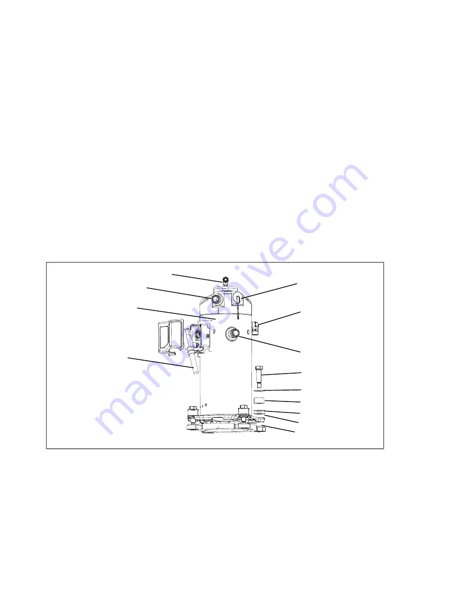
12. Wire tie the compressor base plate to the compressor, and then slide the new compressor into the unit (see
).
Figure 7.5 Compressor Kit
1) Compressor
2) Teflon Seal for Valve Connection (2)
3) O-Ring (Unloader Connection)
4) Compressor Discharge Temperature
Sensor
5) O-Ring (Economizer Connection)
6) Base Mounting Bolts
7) SST Washers
8) Resilient Mount
9) Mylar Washers
10) Wire Ties
11) Power Cable Gasket
12) Ground Connection Screw
- - - - -
NOTE
DO NOT add any oil to the replacement compressor. Replacement compressor is shipped with full oil
charge of 60 oz.
Power Cable Lubricant -
Krytox (Not Shown)
Содержание Transicold 69NT40-561-001
Страница 2: ......
Страница 4: ......
Страница 14: ......
Страница 22: ......
Страница 36: ......
Страница 92: ......
Страница 159: ...7 47 T 340...
Страница 163: ...8 3 T 340 Figure 8 2 Schematic Diagram for Standard Unit Configuration Based on Drawing 62 11271 Rev A...
Страница 169: ...8 9 T 340 Figure 8 8 Schematic and Diagram for Lower Vent Position Sensor VPS Option...
Страница 170: ...T 340 8 10 Figure 8 9 Unit Wiring Diagram for Standard Unit Configuration With 3 Phase Condenser Fan Motors...
Страница 172: ...T 340 8 12 Figure 8 10 Unit Wiring Diagram for Single Phase Condenser Fan Motor and Optional Heater...
Страница 173: ...8 13 T 340 Unit Wiring Diagram for Single Phase Condenser Fan Motor and Optional Heater Based on Drawing 62 66721...
Страница 174: ...T 340 8 14 Figure 8 11 Unit Wiring Diagram for Configuration With eAutoFresh and Emergency Bypass Options...
Страница 176: ......
Страница 180: ......
Страница 181: ......


