


5–13
T-340
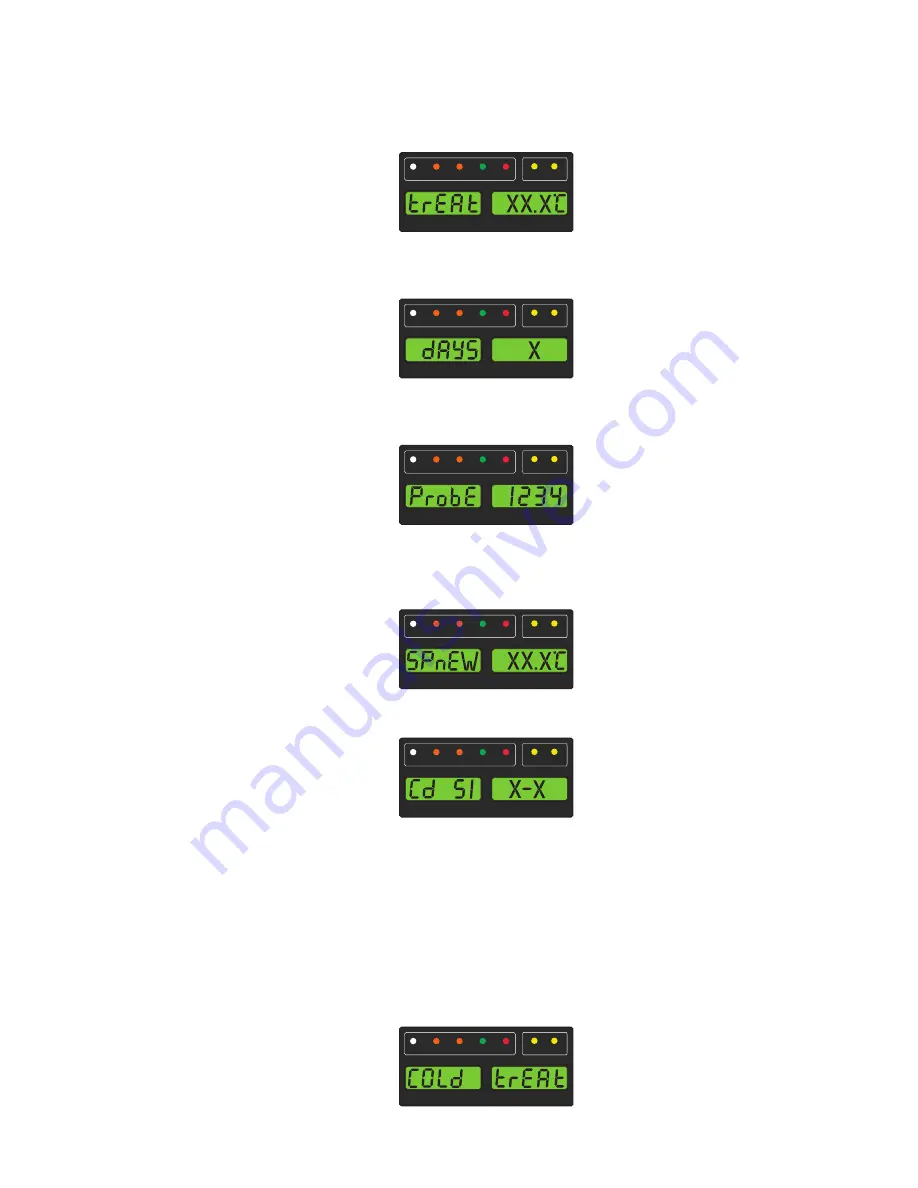
NOTE
"trEAt" is the maximum value that the USDA probes need to remain below, to pass the Cold Treatment pro
-
tocol. For instance, if the treat value is set at 35.0°F (1.7°C) then the USDA probe temperatures must
remain below 35.0°F (1.7°C) to pass.
6. "dAyS" is now displayed in the left display and the right will be flashing. Use the Arrow keys to select the
desired days for cold treatment and press the ENTER key.
7. "ProbE" is now displayed in the left display and the right will display the probe numbers that are connected.
Press the ENTER key. For instance, if "1234" is displayed, then all four of the probes are connected.
8. "SPnEW" is now displayed in the left display and the right will be flashing. Use the Arrow keys to select the
desired setpoint after the cold treatment process has successfully completed and press the ENTER key.
This would be the final temperature prior to the delivery of the cargo.
9. Cd51 is now displayed in the left display and the right will display days / hours remaining in cold treatment.
10. The unit will start to countdown once all detected USDA probes have reached the specified cold treatment
temperature. The cold treatment process will continue until the specified number of days is reached. During
operation, Cd51 will show the number of days and hours remaining in the cold treatment.
NOTE
Once the cold treatment process has been initiated, setpoint change via the keypad is disabled.
11. While the unit is operating in ACT mode, the left hand display will alternate between "COLd" and setpoint.
The right hand display will alternate between "trEAt" and the cargo temperature. Once the treatment time
has been completed, the setpoint temperature will increase to the "SPnEW" setting chosen in step 8.
COOL
HEAT
DEFROST
IN RANGE
ALARM
SUPPLY RETURN
SETPOINT/Code
AIR TEMPERATURE/Data
COOL
HEAT
DEFROST
IN RANGE
ALARM
SUPPLY RETURN
SETPOINT/Code
AIR TEMPERATURE/Data
COOL
HEAT
DEFROST
IN RANGE
ALARM
SUPPLY RETURN
SETPOINT/Code
AIR TEMPERATURE/Data
COOL
HEAT
DEFROST
IN RANGE
ALARM
SUPPLY RETURN
SETPOINT/Code
AIR TEMPERATURE/Data
COOL
HEAT
DEFROST
IN RANGE
ALARM
SUPPLY RETURN
SETPOINT/Code
AIR TEMPERATURE/Data
COOL
HEAT
DEFROST
IN RANGE
ALARM
SUPPLY RETURN
SETPOINT/Code
AIR TEMPERATURE/Data
Содержание Transicold 69NT40-561-001
Страница 2: ......
Страница 4: ......
Страница 14: ......
Страница 22: ......
Страница 36: ......
Страница 92: ......
Страница 159: ...7 47 T 340...
Страница 163: ...8 3 T 340 Figure 8 2 Schematic Diagram for Standard Unit Configuration Based on Drawing 62 11271 Rev A...
Страница 169: ...8 9 T 340 Figure 8 8 Schematic and Diagram for Lower Vent Position Sensor VPS Option...
Страница 170: ...T 340 8 10 Figure 8 9 Unit Wiring Diagram for Standard Unit Configuration With 3 Phase Condenser Fan Motors...
Страница 172: ...T 340 8 12 Figure 8 10 Unit Wiring Diagram for Single Phase Condenser Fan Motor and Optional Heater...
Страница 173: ...8 13 T 340 Unit Wiring Diagram for Single Phase Condenser Fan Motor and Optional Heater Based on Drawing 62 66721...
Страница 174: ...T 340 8 14 Figure 8 11 Unit Wiring Diagram for Configuration With eAutoFresh and Emergency Bypass Options...
Страница 176: ......
Страница 180: ......
Страница 181: ......