7
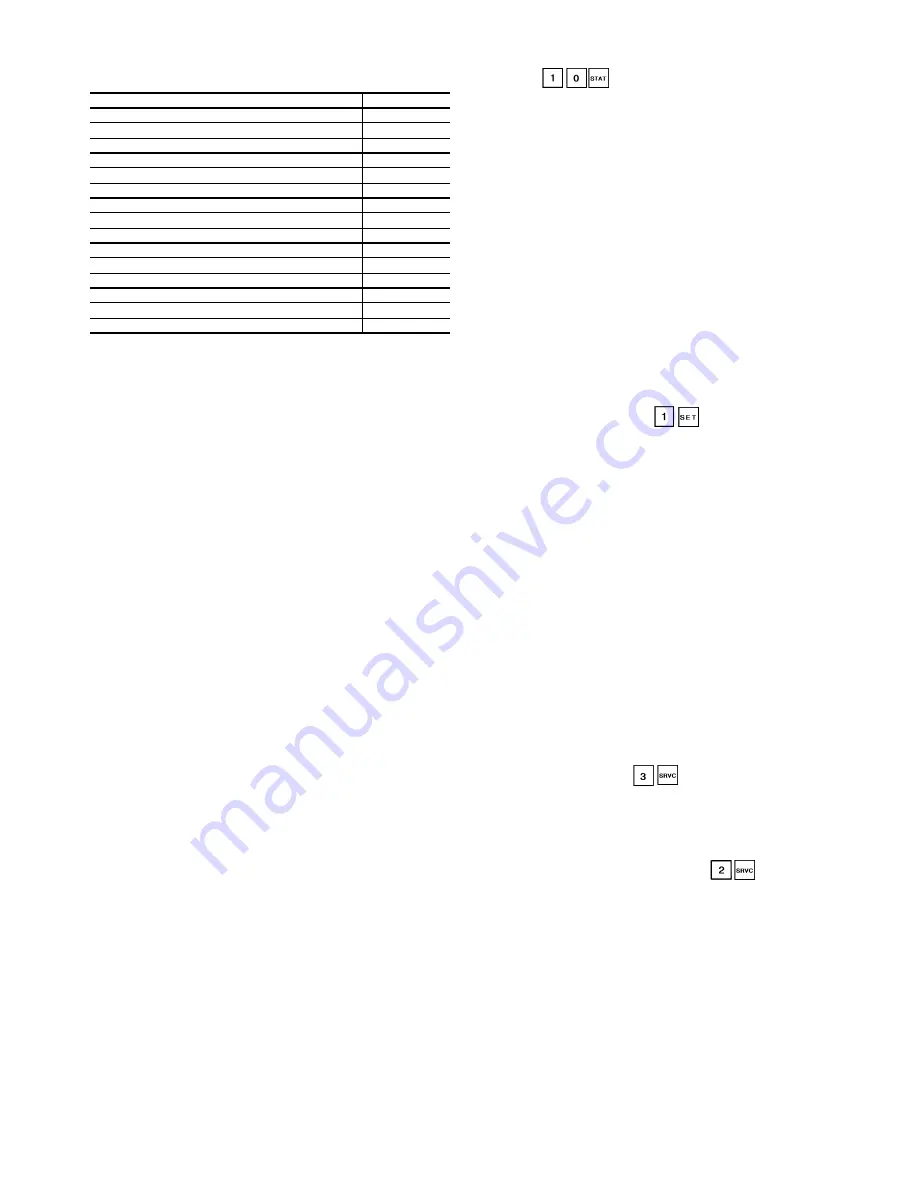
Table 5 — Compressor Protection Module
Feedback Codes
Wye-Delta vs Across-the-Line (XL) Starting
Option —
All 30GX,HX chillers operating at voltages of
208/230-3-60 or 230-3-50 (5 or 8 at Position 12 in model num-
ber) are supplied with factory installed Wye-Delta starters. All
other voltage options can be ordered with either Wye-Delta or
XL starting options. The XL starting method is the most cost
effective and simply starts the compressor motor in a Delta
configuration (the motors are designed for continuous opera-
tion in this configuration) using a single contactor. See Fig. 2.
This is the simplest starting method to use and is ideal where
starting current does not require limiting.
Where current limitations exist, the Wye-Delta option may
be used. See Fig. 3. This option uses a factory-installed starter
assembly for each compressor, which consists of 3 contactors
labelled 1M, 2M, and S. As the compressor is started, the CPM
module energizes contactors 1M and S, which connects and
energizes the motor windings in a Wye configuration. The
starting current required will be approximately 60% less than
that required for an XL start due to the higher impedance of the
motor windings when Wye connected. The compressor will at-
tain about 100% of its normal operating speed (approximately
3 to 5 seconds) before the CPM module deenergizes the S con-
tactor and energizes the 2M contactor, switching the compres-
sor windings to a Delta wiring configuration. The S and 2M
contactors in the starter assembly are both mechanically and
electrically interlocked so that they will not both be energized
at the same time.
Do not alter the factory-installed power wiring from the
control box terminal block to the compressor junction block.
Doing so will cause permanent damage to the compressor and
will require that the compressor be replaced.
Capacity Control —
The control system cycles com-
pressors, loaders, and minimum load control valves to maintain
the user-configured leaving chilled fluid temperature set point.
Entering fluid temperature is used by the microprocessor to de-
termine the temperature drop across the cooler and is used in
determining the optimum time to add or subtract capacity stag-
es. The chilled fluid temperature set point can be automatically
reset by the return temperature reset or space and outdoor-air
temperature reset features. It can also be reset from an external
4 to 20 mA signal (requires field-supplied 500-ohm,
1
/
2
watt re-
sistor), or from a network signal.
The capacity control algorithm runs every 30 seconds. The
algorithm attempts to maintain the Control Point at the desired
set point. Each time it runs, the control reads the entering and
leaving fluid temperatures. The control determines the rate at
which conditions are changing and calculates 2 variables based
on these conditions. Next, a capacity ratio (Load/Unload Factor
under
) is calculated using the 2 variables to deter-
mine whether or not to make any changes to the current stages
of capacity. This ratio value ranges from –100 to + 100%. If the
next stage of capacity is a compressor, the control starts (stops)
a compressor when the ratio r 100% (–100%). If the
next stage of capacity is a loader, the control energizes (deener-
gizes) a loader when the ratio r 60% (–60%). Loaders
are allowed to cycle faster than compressors, to minimize the
number of starts and stops on each compressor. A delay of
90 seconds occurs after each capacity step change.
MINUTES LEFT FOR START — This value is displayed in
the Status subfunction and represents the amount of time to
elapse before the unit is started. This value can be zero without
the machine running in many situations. This can include
being unoccupied, LOR switch in the OFF position, CCN not
allowing unit to start, Demand Limit in effect, no call for cool-
ing due to no load, and alarm or alert conditions present. If the
machine should be running and none of the above are true, a
minimum off time may be in effect. The machine should start
normally once the time limit has expired.
MINUTES OFF TIME (
) — This user configurable
time period is used by the control to determine how long unit
operation is delayed after power is applied/restored to the unit.
It is also used to delay compressor restarts after the unit has
shut off its lowest stage of capacity. Typically, this time period
is configured when multiple machines are located on a single
site. For example, this gives the user the ability to prevent all
the units from restarting at once after a power failure. A value
of zero for this variable does not mean that the unit should be
running.
LOADING SEQUENCE — The 30GX,HX compressor effi-
ciency is greatest at full load. Therefore, the following
sequence list applies to capacity control.
1. The next compressor is not started until all others are run-
ning at 100%.
2. The second unloading stage is only used during initial
capacity staging of the unit at start-up.
3. Whenever a compressor is started in a circuit, the loaders in
the circuit are deenergized for 15 seconds before the com-
pressor is started. The loaders are energized 90 seconds after
the compressor is started.
CLOSE CONTROL (
) — When configured for Close
Control, the control is allowed to use any loading/capacity con-
trol devices required to maintain better leaving fluid tempera-
ture regulation. All stages of unloading are available. See
Appendix B for an example.
LEAD/LAG DETERMINATION (
) — This is a con-
figurable choice and is factory set to be automatic. The value
can be changed to Circuit A or Circuit B leading, as desired.
Set at automatic, the control will sum the current number of
logged circuit starts and one-quarter of the current operating
hours for each circuit. The circuit with the lowest sum is
started first. Changes to which circuit is the lead circuit and
which is the lag are made when shutting off compressors.
On 30HX206-271 and 30GX205-350 units set for staged
loading, the control fully loads the lead circuit before starting
the lag circuit and unloads the lag circuit first. When these units
are set for equal loading, the control maintains nearly equal
capacities in each circuit when the chiller is loading and
unloading.
ALARM CONDITION
VALUE
High Pressure Switch Trip
1.0
No Motor Current
2.0
Current Imbalance Alarm 10%
2.5
Current Imbalance Warning 10%
2.7
Current Imbalance 25%
3.0
Single Phase Current Loss
3.5
High Motor Current
4.0
Ground Fault
5.0
Contactor Failure
7.5
Current Phase Reversal
8.0
Motor Overtemperature
8.5
Open Thermistor
9.0
Configuration Header Fault
9.5
Shorted Thermistor
10.0
No Error
0


