


60
BURNOUT CLEAN-UP PROCEDURE — If a screw com-
pressor motor burns out on a 30GX,HX chiller, a simple clean-
up should be performed. The following procedure provides the
minimum steps to be taken before restarting the circuit.
1. Remove the oil from the oil separator. This can be facili-
tated by connecting a hose to the port located on the ser-
vice valve entering the external oil filter. Run the hose to a
container(s) that can hold up to 5 to 6 gallons (19 to 20 L)
of oil. To force out most of the oil in the separator pressur-
ize the circuit. To remove the remaining oil, the pre-lube
pump can be run in
mode from the HSIO. To pre-
vent wear to the gears, do not allow the pre-lube pump to
operate “dry.”
2. Remove the failed compressor following the Compressor
Changeout Sequence procedure above.
3. Once the compressor is removed access the oil catch pan
through the cooler-compressor mounting flange. Clean out
any debris which may have collected in the oil catch pan.
4. Install a new compressor.
5. To dilute and remove any residual oil left in the separator,
pump approximately
1
/
2
gallon (2 L) of compressor oil
into the oil separator using the Schrader port located on
top of the separator (30GX) or on the discharge line
(30HX) and remove using the pre-lube pump described in
Step 1.
6. Disconnect the hose from the external oil filter service
valve.
7. Install a new filter drier and compressor external oil filter.
8. Measure in the amount of Castrol SW 220 Polyolester oil
as specified on the nameplate of the chiller.
9. Leak check, evacuate and recharge the machine as
described in this manual with the amount of R-134a stated
on the chiller nameplate.
10. Perform periodic acid checks on the circuit and change the
filter drier in the motor cooling line as necessary. Use the
Carrier Standard Service Techniques Manual as a source
of reference.
Moisture-Liquid Indicator —
Clear flow of liquid
refrigerant indicates sufficient charge in the system. Note,
however, that bubbles in the sight glass do not necessarily indi-
cate insufficient charge. Moisture in the system is measured in
parts per million (ppm), changes of color of indicator are:
Green — moisture is below 80 ppm;
Yellow-green (chartreuse) — 80 to 225 ppm (caution);
Yellow (wet) — above 225 ppm.
Change filter drier at the first sign of moisture in the system.
Filter Drier —
Whenever moisture-liquid indicator shows
presence of moisture, replace filter drier. Refer to Carrier
Standards Service Technique Manual, Chapter 1, Refrigerants,
for details on servicing filter driers. Cleanable strainers have
been installed in each circuit’s liquid line to aid in removal of
system contaminants and debris.
Liquid Line Service Valve —
This valve is located
ahead of the filter drier and provides a
1
/
4
-in. Schrader connec-
tion (30GX only) for field charging. In combination with com-
pressor discharge service valve, each circuit can be pumped
down into the high side for servicing.
IMPORTANT: Unit must in operation for at least
12 hours before moisture indicator can give an accurate
reading. With the unit running, the indicating element
must be in contact with liquid refrigerant to give true
reading.
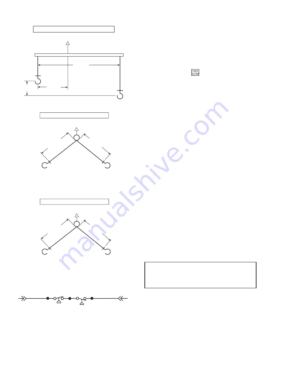
CENTER OF GRAVITY
OF COMPRESSOR
DISCHARGE END
GEAR COVER END
MINIMUM
381 mm
(15 in.)
MINIMUM
381 mm
(15 in.)
COMPRESSOR LIFTING MECHANISM
DISCHARGE END
GEAR COVER END
CENTER OF GRAVITY
OF COMPRESSOR
508 mm
(20.0 in.)
178 mm
(7.0 in.)
95 mm
(3.75 in.)
CENTER OF GRAVITY
OF COMPRESSOR
MINIMUM
300 mm
(11.8 in.)
MINIMUM
384 mm
(15.1 in.)
COMPRESSOR LIFTING MECHANISM
COMPRESSOR SIDE
MOTOR SIDE
HPS
RRS
NOTE: Locate strap from center of gravity lifting ring and support
motor casing to provide 3-point level rigging.
Fig. 20 — Compressor Lifting Diagrams
Fig. 21 — Reverse Rotation Switch Wiring
LEGEND
HPS — High-Pressure Switch
PL
— Plug
RRS — Reverse Rotation Switch
COMPRESSOR LIFTING MECHANISM
LIFTING LUGS BOTH OUTSIDE EDGES
LIFTING LUGS BOTH OUTSIDE EDGES
EQUIDISTANT FROM GEAR COVER END
ONE LUG AT OUTSIDE EDGE, RING AT
DISCHARGE CENTER


