256
entering adjoining equipment, perform the cleaning in an
-
other room.
4. Replace the cooling fan.
5. Restore power.
MAIN FAN REPLACEMENT
The main cooling fan of the VFD has a life span of about 60,000
operating hours at maximum rated operating temperature and
drive load. The expected life span doubles for each 18°F drop in
the fan temperature (fan temperature is a function of ambient tem
-
peratures and drive loads).
Fan failure can be predicted by the increasing noise from fan bear
-
ings and the gradual rise in the heat sink temperature in spite of
heat sink cleaning. If the drive is operated in a critical part of a
process, fan replacement is recommended once these symptoms
start appearing. Replacement fans are available from Carrier.
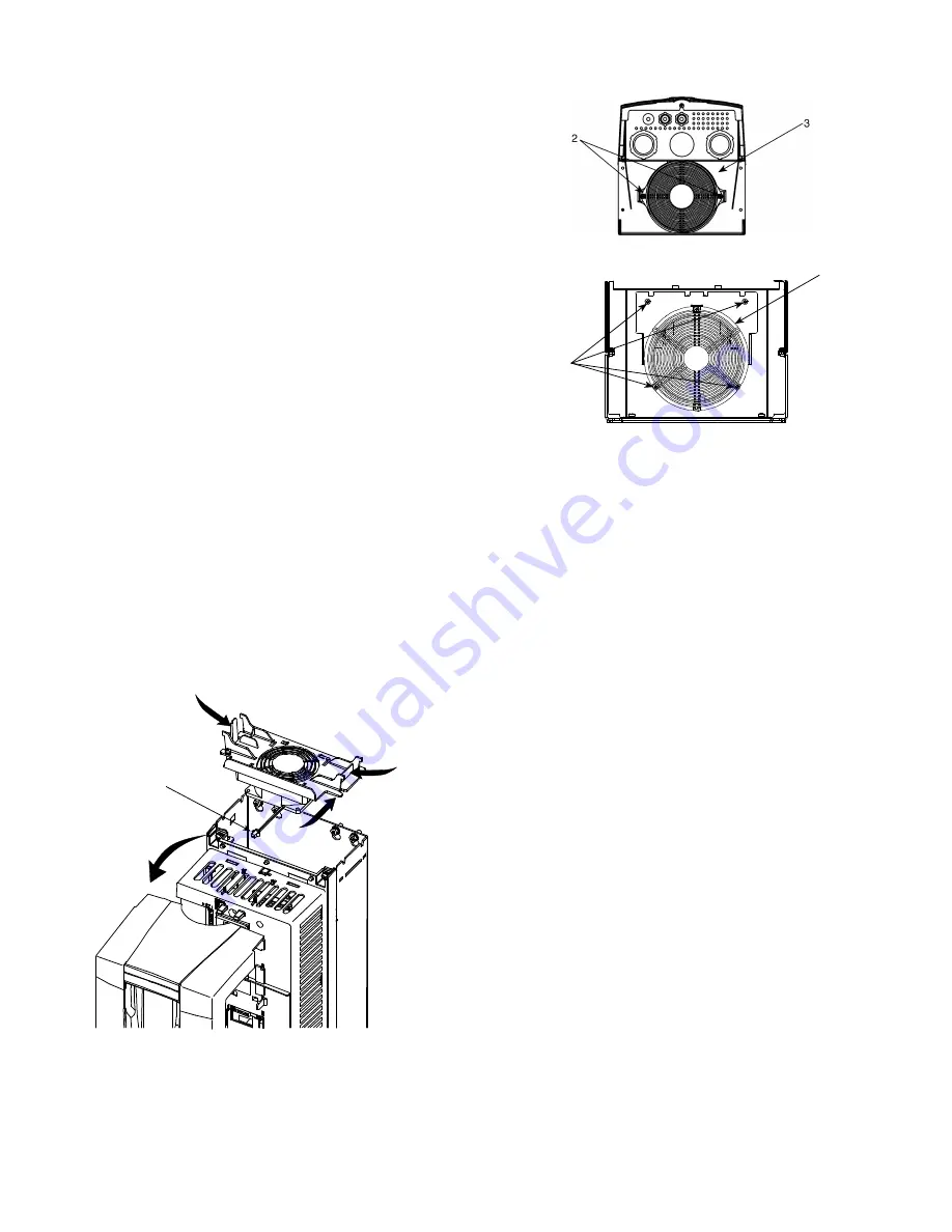
To replace the main fan for frame sizes R1 through R4, perform
the following (see Fig. 212):
1. Remove power from drive.
2. Remove drive cover.
3. For frame sizes R1 and R2, press together the retaining
clips on the fan cover and lift. For frame sizes R3 and R4,
press in on the lever located on the left side of the fan
mount, and rotate the fan up and out.
4. Disconnect the fan cable.
5. Install the new fan by reversing Steps 2 to 4.
6. Restore power.
To replace the main fan for frame sizes R5 and R6, perform the
following (see Fig. 213):
1. Remove power from drive.
2. Remove the screws attaching the fan.
3. Disconnect the fan cable.
4. Install the fan in reverse order.
5. Restore power.
CONTROL PANEL CLEANING
Use a soft damp cloth to clean the control panel. Avoid harsh
cleaners which could scratch the display window.
BATTERY REPLACEMENT
A battery is only used in assistant control panels that have the
clock function available and enabled. The battery keeps the clock
operating in memory during power interruptions. The expected
life for the battery is greater than ten years. To remove the battery,
use a coin to rotate the battery holder on the back of the control
panel. Replace the battery with type CR2032.
TROUBLESHOOTING
Steam Coil Performance Problems
Coil capacity is normally not a problem with steam coils. Low ca
-
pacity can result from blocked or plugged air side surface, an air
bound coil, or a coil which is filled with condensate because of a
non-functioning steam trap. The Carrier steam coils with the 1-in.
OD outer tube have at least twice the condensate loading capacity
of a coil with
5
/
8
-in. OD outer tubes.
Water hammer can damage the coil and cause leaks. It is typically
caused by improper piping of the steam supply, allowing conden
-
sate to enter the coil with the steam supply; or by accumulation of
condensate in the coil which can occur with the coils operating at
partial load without a vacuum breaking device.
Problems with temperature control can occur when a thermostatic
controller or steam control valve is not functioning properly. Tem
-
perature control problems will also occur when the steam controls
valve is oversized. Consider
1
/
3
to
2
/
3
valve arrangements for full
range control.
Problems with “water logging” of the condensate tubes can occur
when a coil with over 6-ft tubes is selected at high air velocities,
low steam pressures (below 5 psig) and high density fin spacing (9
fins per inch or more). This high density fin spacing, while pro
-
ducing high levels of heating capacity, also promotes excessive
condensate. Given the length of the tubes and the low steam sup
-
ply pressure, condensate can build up faster than the drain system
can carry it away. Considerations should be given for using two
coils in series for this application.
3
3
4
2
a39-2922
Fig. 212 —
Main Fan Replacement
(Frame Sizes R1 - R4)
2
3
Fig. 213 —
Main Fan Replacement
(Frame Sizes R5 and R6)
BOTTOM VIEW (R5)
BOTTOM VIEW (R6)


