


210
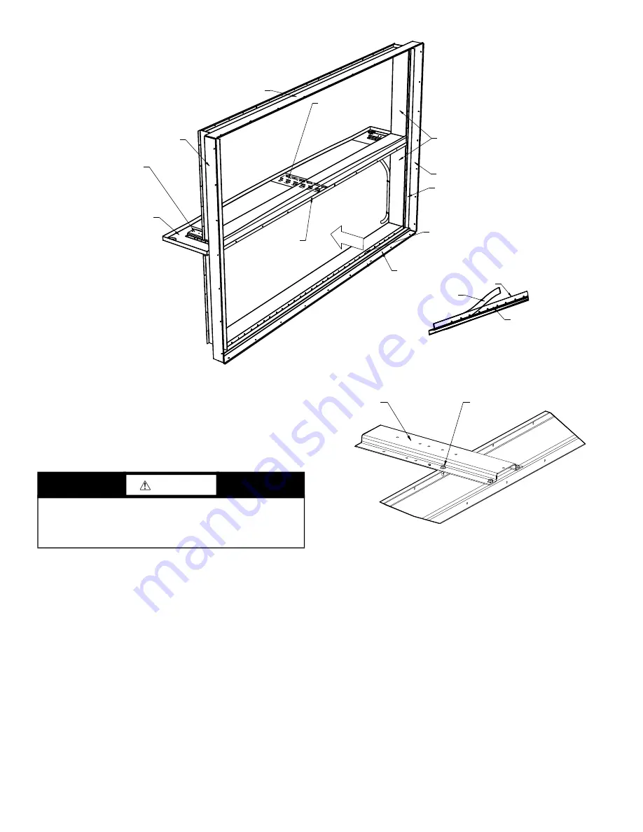
12. Remove the fastening screws of the lowermost coil from
the upstream side. Note that the fastening screws pass
through the vertical angle, baffles, and coil casing. See
Fig. 195. Removal of the fastening screws may require
reaching through an opened damper assembly, reaching
through a filter track after filters are removed, or remov
-
ing a coil immediately upstream.
13. Slip the foam sealing sleeves off the connection nipples
before removing the coil and set the sleeves aside.
14. The lower coil may now be hoisted out through the top
opening, or carefully slid out either side of the cabinet.
15. Inspect the adhesive backed gasket applied to the lower
baffle, spanning the entire unit, on the surface that con
-
tacts the coil (see Fig. 195). If damaged, remove the re
-
mainder of the old gasket and replace.
Changing Coil Hand
NOTE: Electric heat coil hand cannot be changed.
NOTE: The coil cover panel is not part of the coil. Remove
cover panel from end of unit. New holes must be cut in coil
cover panel. Original holes must be plugged and insulated.
New side panels may be necessary when changing coil hand.
NUFIN COILS
The NuFin coil is airflow direction sensitive, especially when used
in dehumidifying applications. Hydronic versions are counterflow
circuited for full gravity draining when installed level.
Correct installation will result in the typical bottom inlet on leav
-
ing air face and top outlet on entering air face of coil, a self-vent
-
ing design. This will ensure cold air contact with cold water, and
warm air with hot water.
Coil repositioning for opposite hand application will compromise
one or more of these characteristics. However, there will be those
situations where this may prove acceptable.
As a general rule, a change from counterflow circuiting to parallel
flow for sensible heating and cooling applications will result in a
5% drop in net capacity per row of coil. In one and two row
BAFFLE, TOP
CHANNEL, HAT
COIL FRAME
S
BAFFLE, RIGHT
ANGLE
ATTACHED TO COIL
S
BOTH
S
IDE
S
BOTTOM BAFFLE
APPLY FLU
S
H TO THI
S
EDGE
GA
S
KET, ADHE
S
IVE
BAFFLE, BOTTOM
IMPORTANT: ADHE
S
IVE GA
S
KET MU
S
T BE
APPLIED TO THE FULL LENGTH OF THE
BOTTOM BAFFLE MATING FLANGE TO
CREATE
S
EAL BETWEEN THE COIL
S
IDE
CA
S
ING AND THE BAFFLE.
S
EE
ILLU
S
TRATION BELOW.
BAFFLE, CENTER
PAN, CONDEN
S
ATE
CENTERED WITHIN
S
ECTION
BAFFLE, LEFT
CHANNEL, HAT
Fig. 195 —
Coil Frames and Baffle
a39-2920
CAUTION
Do not handle the coil by the headers or connection nipples, as
irreparable damage might occur that is NOT covered by war
-
ranty. Protect the finned surface from damage during all han
-
dling and shipping.
ATTACH WITH 4
S
CREW
S
TO COIL CA
S
ING
CHANNEL, HAT
Fig. 196 —
Spacer (Hat Channel)
a39-2921


