


39
ALARMS
Alarms inform the user that there is an operational problem with
the unit. Some alarms will result in the unit shutting down, some
will shut down only the affected equipment, and some are infor
-
mational only. The 100 most recent alarms (active or cleared)
can be viewed on the Alarm Status screen on the Equipment
Touch device.
Alarm Status
When an alarm is active, the alarm icon (exclamation mark) back
-
ground on the Home screen is red to indicate an alarm condition.
See Fig. 62.
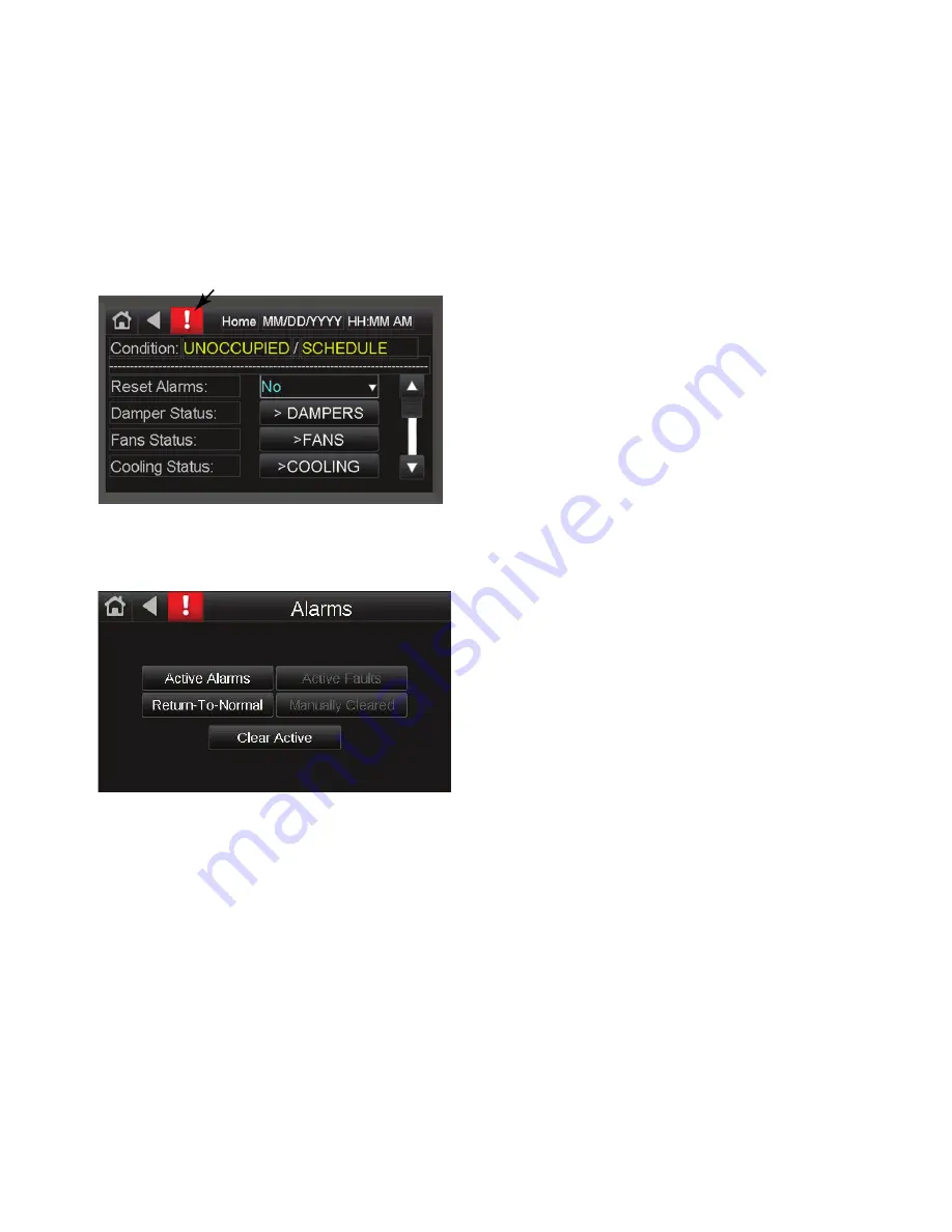
Fig. 62 — Alarm Icon
To access the alarm information, press the red alarm icon on the
Home page touchscreen. Press the alarm icon twice to access the
Alarms Screen options. See Fig. 63.
Fig. 63 — Alarms Screen
CLEARING ALARMS
When an alarm event occurs, an audible alarm (touchscreen setup
option) will sound and the Equipment Touch will log the event on
the Active Alarms. Press the alarm icon to display the active
alarms list. To access the menu page, press the alarm icon again.
Press Clear Active alarms to reset alarms. See Fig. 63.
The alarm will remain active until it is cleared. If the alarm is an
automatically re-settable alarm, it will be cleared as soon as the
condition which initiated it is corrected. To clear an active alarm
press Clear Active.
If an alarm is automatically cleared, it will be removed from the
Active Alarms section and moved to the Returned-to-Normal sec
-
tion. If the alarm is manually cleared it will be moved to the Man
-
ually Cleared section. Refresh the screen by pressing the Reset
Alarms button on the Home screen.
Alarm Matrix
Table 9 lists the possible alarm events which can be displayed in
the Alarm Status screen of the Equipment Touch and Table 10 lists
the condition/mode statuses which might be displayed to indicate
the Alarm condition/mode of the unit. These are classified as auto
-
matically and manually re-settable alarms.
AUTOMATIC RESET
These alarms are reset automatically after the condition which ini
-
tiated the alarm is corrected. Then they will show up under the Re
-
turn-to-Normal section of the history. Refresh the screen to see the
change. If the condition which initiated the alarm is not corrected,
the alarm will be reissued. Table 9 lists the automatic reset alarms.
MANUAL RESET
These alarms are reset manually from the Equipment Touch (see
“Clearing Alarms”) or after cycling the power on the OEM. Then
they will show up under the “Returned-to-Normal” section of the
history. In which case they will show up under the “Manually
Cleared” section of the history. If the condition which initiated the
alarm is not corrected, the alarm will be reissued. Table 10 lists the
manual reset alarms.
ALARMS AFTER STARTUP
Alarms may occur after startup due to a variety of factors. Always
check that all sensors and inputs are properly connected.
SAFETY SWITCHES
• High Pressure Switch (HPS1): If HPS1 is open, compres
-
sor #1 will turn off and the OEM controller will issue an
alarm. After manually resetting HPS1, the HPS1 alarm
will reset. Following a minimum time off delay, compres
-
sor #1 will turn on. If the OEM controller records 3 high
pressure start/restart failure incidents within 1 hour, com
-
pressor #1 is locked out and the OEM controller will issue
an alarm. The compressor lock-out can be reset in the
Equipment Touch or by cycling the power of the OEM
controller. Refer to the Installation, Operation and Mainte
-
nance (IOM) Instructions for more information.
NOTE: For systems with two circuits, this is the same for
compressor #2, Y2 and HPS2.
• Low Pressure Switch (LPS1): If LPS1 is open after the
LPS1 by-pass time, the OEM controller will issue an alarm
and compressor #1 turns off. After 30 seconds (fixed), the
LPS1 alarm will reset. Following the minimum time-off
delay, the compressor #1 will turn on. If the OEM control
-
ler records 3 low pressure start/restart failure incidents
within 1 hour, compressor #1 is locked out and the OEM
controller will issue an alarm. The compressor lock-out
can be reset in the Equipment Touch or by cycling the
power of the OEM controller. Refer to the IOM for more
information.
Note: For systems with two circuits, this is the same for
compressor #2, Y2 and LPS2.
SAFETY SHUTDOWN
• Smoke Detector (Optional): When a smoke detector (SD)
is provided, it is wired directly to the OEM controller. If
smoke is detected, the OEM controller will shut down the
unit. The alarm can be reset in the Equipment Touch or by
cycling the power of the OEM controller.
• High pressure switch lockout: A compressor fails to start 3
times in an hour due to high pressure switch lock out. The
alarm can be reset in the Equipment Touch or by cycling
the power of the OEM controller.
• Low pressure switch lockout: A compressor fails to start 3
times in an hour due to low pressure switch lock out. The
alarm can be reset in the Equipment Touch or by cycling
the power of the OEM controller.
• DX LAT or suction line temperature lock out: A compres
-
sor fails to start 3 times in an hour due to DX LAT or suc
-
tion line temperature lock out. The alarm can be reset in
the Equipment Touch or by cycling the power of the OEM
controller.
• SAT sensor failure: The OEM controller detects an SAT
sensor failure. The alarm can be reset in the Equipment
Touch or by cycling the power of the OEM controller.
ALARM
ICON


