


25
ADDING NEW LOCAL SCHEDULES
NOTE: Local schedules will only be effective if the unit occupan
-
cy control is configured for local schedule. See Tech Setup screen
for configuration options.
1. Click on the
button next to Add Schedule to add a new
schedule.
2. Choose On Schedule (Occupied) or Off Schedule (Unoccu
-
pied).
3. Choose Schedule Priority Type: Normal or Override.
4. Choose Schedule Type: Dated, Weekly, or Continuous.
5. Determine Start and End Time and Date of Schedule.
6. Save the schedule. The system uploads the schedule to the
controller.
ADDING MULTIPLE PERIODS TO A SCHEDULE
A weekly schedule can have multiple periods. For example, the
first period could be every Monday through Friday, 8:00 am to
5:00 pm. The second periods could be every Monday through
Wednesday 6:00 pm to 8:00 pm. You can create up to 4 period for
a day, and up to 28 periods for a week.
1. Create a weekly schedule for the first period. See Adding
New Local Schedule.
2. In the Schedules screen, touch the green bar for the schedule
to which a period should be added.
3. In the Schedule (day View) screen, touch the schedule name
or green bar (not the Effective Schedule bar) and press Next.
4. Press +Period.
5. Set the times and days for the new period; for example, Mon
-
day through Wednesday, 6:00 pm to 8:00 pm.
6. Save the period.
Sensor Calibration
The Sensor Calibration screen (
Home
Setup
Calibration
) dis
-
plays the calibration settings for unit sensors. See Fig. 35.
Fig. 35 — Calibration
The calibration screen can be used to adjust the effective sensor
reading by a fixed off set (+ or -) if the unit sensor reading is dif
-
ferent from a known reading source. Applying offsets can also be
useful for unit troubleshooting to influence unit operation (force
the unit into a mode) or to quickly determine a faulty sensor.
Faulty temperature sensors will typically display a value of –60°F
(open) or 296°F (short).
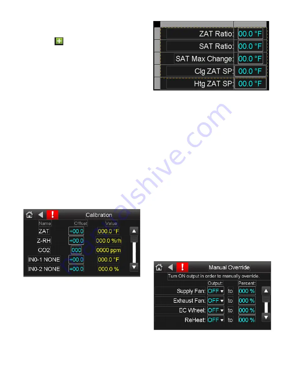
SUPPLY AIR TEMPERATURE (SAT) RESET
The SAT reset screen (
Home
Setup
Calibration
) displays the
set points for SAT reset operation. See Fig. 36.
Fig. 36 — SAT Reset Set Points
The SAT reset functions operates based on user configured set
points and a referenced temperature. See the Tech Settings screen
(
Home
Setup
Tech Setup
) to set and select the method of op
-
eration.
• ZAT/OAT Ratio - ratio that the ZAT/OAT deviation from
set point has on the SAT
• SAT Ratio - ratio that the SAT is reset based on the ZAT
ratio
• SAT Max Change - maximum reset amount
• Clg ZAT/OAT SP - zone air temp or outdoor air temp set
point for cooling operation
• Htg ZAT/OAT SP - zone air temp or outdoor air temp set
point for heating operation
SAT RESET OPERATION
When SAT reset is enabled, the unit is in the appropriate mode
based on the configuration (cooling, heating, or dehum), and the
zone air temp is above or below the zone air temp set point, SAT
reset is activated. The supply air temperature set point is reset by
the SAT ratio based on the ZAT deviation from ZAT set point and
the ZAT ratio.
Based on the settings in Fig. 36, if the unit was configured for SAT
Reset - ZAT CLG and the zone air temp 72°F (2°F above the cool
-
ing ZAT set point of 70°F), the unit would enter SAT reset mode.
Since the SAT ratio is 3°F SAT for every 1°F ZAT, the SAT would
be reset down by 6°F, up to a maximum of 10°F.
Manual Override
The Manual Override screen (
Home
Setup
Man Ovrd
) dis
-
plays the settings for overriding modulating components. See
Fig. 37.
Fig. 37 — SAT Reset Set Points
The Manual Override screen can be used to override the modula
-
tion for a component when the component is operating. Manual
overrides can be useful for troubleshooting or for unit start-up. It's


